Asus P5GD1-VM P5GD1-VM User's manual English Edition E1881 - Page 43
Power LED Lead 3-1 pin PLED1
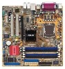 |
View all Asus P5GD1-VM manuals
Add to My Manuals
Save this manual to your list of manuals |
Page 43 highlights
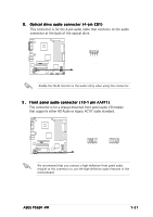
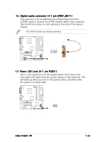
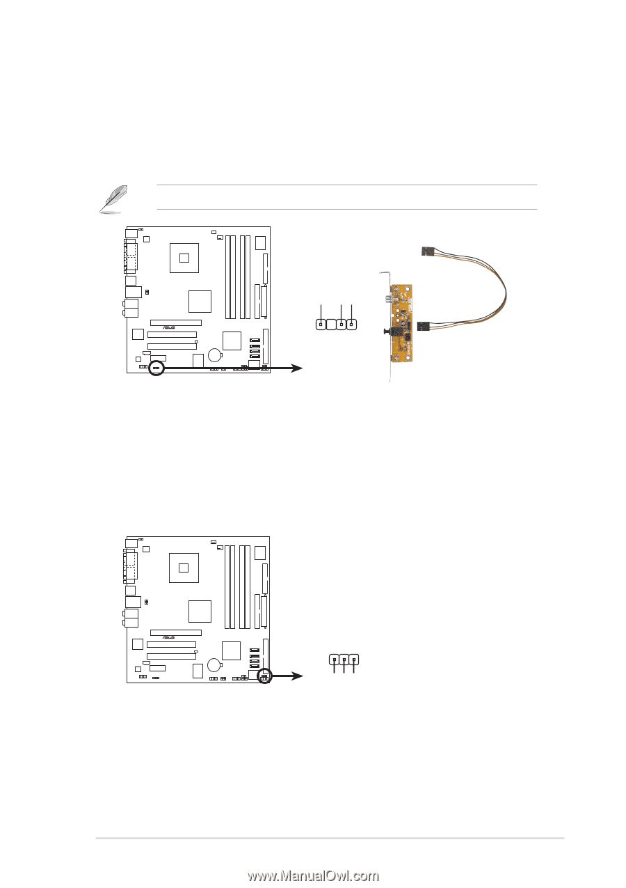
12. Digital audio connector (4-1 pin SPDIF_OUT1) This connector is for an additional Sony/Philips Digital Interface (S/PDIF) port(s). Connect the S/PDIF module cable to this connector, then install the module to a slot opening at the back of the system chassis. The S/PDIF module is purchased separately. P5GD1-VM +5V SPDIFOUT GND ® SPDIF_OUT1 P5GD1-VM Digital audio connector 13 Power LED Lead (3-1 pin PLED1) This 3-1 pin connector is for the system power LED. Connect the 3-pin power LED cable from the system chassis to this connector. The LED lights up when you turn on the system power, and blinks when the system is in sleep mode. P5GD1-VM PLED+ NC PLED- ® P5GD1-VM PLED setting PLED1 1 ASUS P5GD1-VM 1-33
-
 1
1 -
2
-
3
-
4
-
5
-
6
-
7
-
8
-
9
-
10
-
11
-
12
-
13
-
14
-
15
-
16
-
17
-
18
-
19
-
20
-
21
-
22
-
23
-
24
-
25
-
26
-
27
-
28
-
29
-
30
-
31
-
32
-
33
-
34
-
35
-
36
-
37
-
 38
38 -
 39
39 -
 40
40 -
 41
41 -
 42
42 -
 43
43 -
 44
44 -
 45
45 -
 46
46 -
 47
47 -
 48
48 -
49
-
50
-
51
-
52
-
53
-
54
-
55
-
56
-
57
-
58
-
59
-
60
-
61
-
62
-
63
-
64
-
65
-
66
-
67
-
68
-
69
-
70
-
71
-
72
-
73
-
74
-
75
-
76
-
77
-
78
-
79
-
80
-
81
-
82
-
83
-
84
-
85
-
86
-
87
-
88
-
89
-
90
-
91
-
92
 |
 |
ASUS P5GD1-VM
ASUS P5GD1-VM
ASUS P5GD1-VM
ASUS P5GD1-VM
ASUS P5GD1-VM
1-33
1-33
1-33
1-33
1-33
P5GD1-VM
P5GD1-VM Digital audio connector
+5V
SPDIFOUT
GND
SPDIF_OUT1
12.
12.
12.
12.
12. Digital audio connector (4-1 pin SPDIF_OUT1)
Digital audio connector (4-1 pin SPDIF_OUT1)
Digital audio connector (4-1 pin SPDIF_OUT1)
Digital audio connector (4-1 pin SPDIF_OUT1)
Digital audio connector (4-1 pin SPDIF_OUT1)
This connector is for an additional Sony/Philips Digital Interface
(S/PDIF) port(s). Connect the S/PDIF module cable to this connector,
then install the module to a slot opening at the back of the system
chassis.
The S/PDIF module is purchased separately.
13
13
13
13
13
Power LED Lead (3-1 pin PLED1)
Power LED Lead (3-1 pin PLED1)
Power LED Lead (3-1 pin PLED1)
Power LED Lead (3-1 pin PLED1)
Power LED Lead (3-1 pin PLED1)
This 3-1 pin connector is for the system power LED. Connect the
3-pin power LED cable from the system chassis to this connector. The
LED lights up when you turn on the system power, and blinks when
the system is in sleep mode.
P5GD1-VM
P5GD1-VM PLED setting
PLED1
PLED+
1
NC
PLED-