Asus V6-P5G41E User Manual - Page 47
P5G41T-M LX2/GB ATX power connectors, ATX power connectors 24-pin EATXPWR, 4-pin ATX12V
 |
View all Asus V6-P5G41E manuals
Add to My Manuals
Save this manual to your list of manuals |
Page 47 highlights
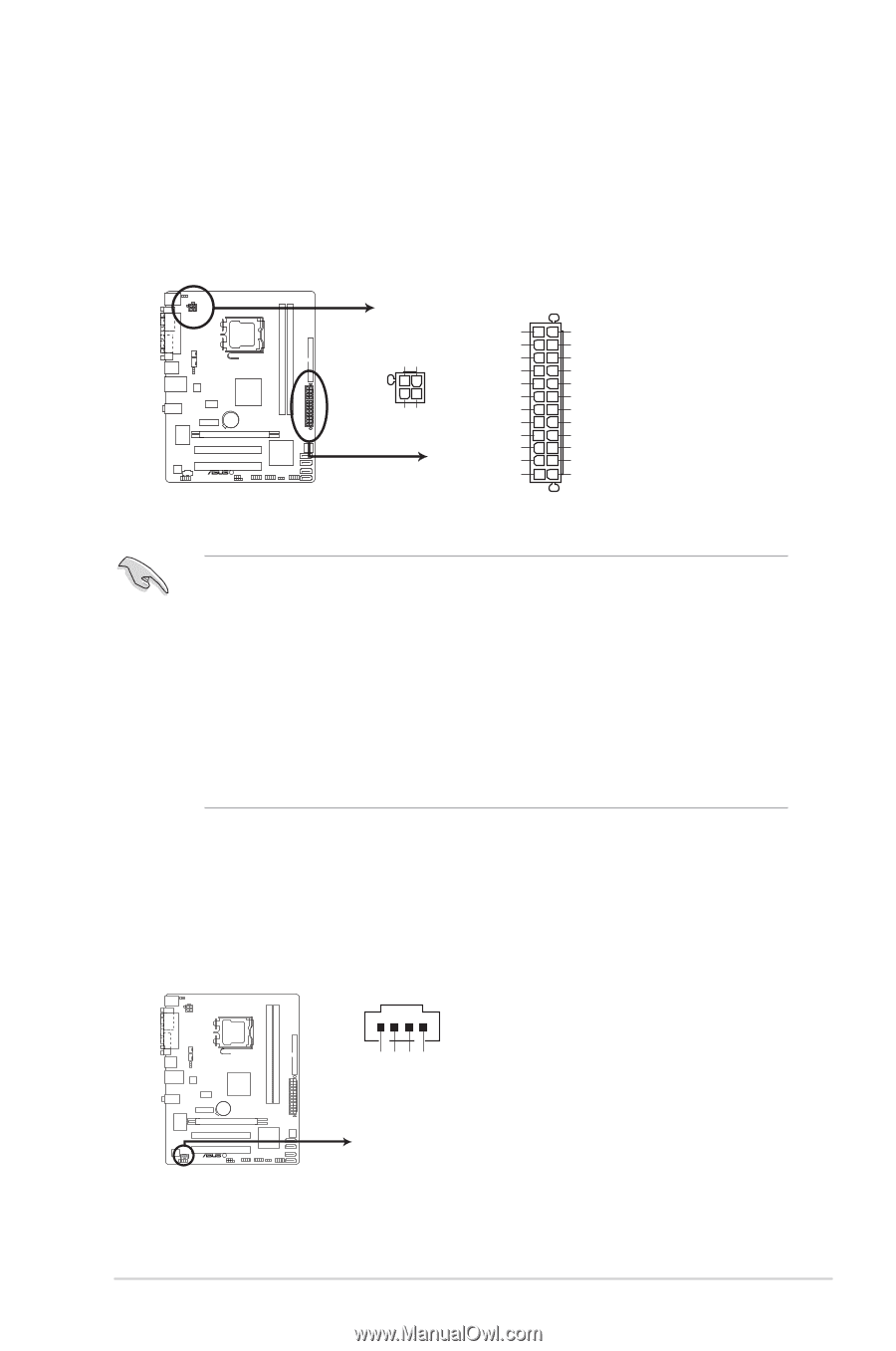
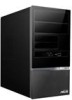
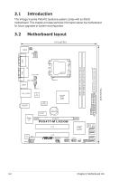
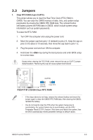
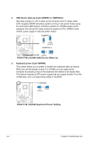
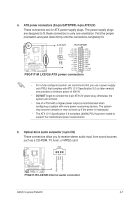
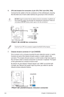
4. ATX power connectors (24-pin EATXPWR, 4-pin ATX12V) These connectors are for ATX power supply plugs. The power supply plugs are designed to fit these connectors in only one orientation. Find the proper orientation and push down firmly until the connectors completely fit. ATX12V EATXPWR +12V DC +12V DC +3 Volts GND +12 Volts +5 Volts +12 Volts +5 Volts +5V Standby +5 Volts Power OK -5 Volts PIN 1 GND +5 Volts GND GND GND GND GND GND P5G41T-M LX2/GB +5 Volts GND PSON# GND +3 Volts -12 Volts +3 Volts +3 Volts PIN 1 P5G41T-M LX2/GB ATX power connectors • For a fully configured system, we recommend that you use a power supply unit (PSU) that complies with ATX 12 V Specification 2.0 (or later version) and provides a minimum power of 400 W. • DO NOT forget to connect the 4-pin ATX12V power plug; otherwise, the system will not boot. • Use of a PSU with a higher power output is recommended when configuring a system with more power-consuming devices. The system may become unstable or may not boot up if the power is inadequate. • The ATX 12 V Specification 2.0-compliant (400W) PSU has been tested to support the motherboard power requirements. 5. Optical drive audio connector (4-pin CD) These connectors allow you to receive stereo audio input from sound sources such as a CD-ROM, TV tuner, or MPEG card. CD Right Audio Channel GND GND Left Audio Channel P5G41T-M LX2/GB P5G41T-M LX2/GB Internal audio connector ASUS V-series P5G41E 3-7
-
 1
1 -
2
-
3
-
4
-
5
-
6
-
7
-
8
-
9
-
10
-
11
-
12
-
13
-
14
-
15
-
16
-
17
-
18
-
19
-
20
-
21
-
22
-
23
-
24
-
25
-
26
-
27
-
28
-
29
-
30
-
31
-
32
-
33
-
34
-
35
-
36
-
37
-
38
-
39
-
40
-
41
-
 42
42 -
 43
43 -
 44
44 -
 45
45 -
 46
46 -
 47
47 -
 48
48 -
 49
49 -
 50
50 -
 51
51 -
 52
52 -
53
-
54
-
55
-
56
-
57
-
58
-
59
-
60
-
61
-
62
-
63
-
64
-
65
-
66
-
67
-
68
-
69
-
70
-
71
-
72
-
73
-
74
-
75
-
76
-
77
-
78
-
79
-
80
-
81
-
82
 |
 |