Behringer DDM4000 Manual - Page 9
Rear panel connectors, Rear panel outputs, Power - dj mixer
 |
View all Behringer DDM4000 manuals
Add to My Manuals
Save this manual to your list of manuals |
Page 9 highlights
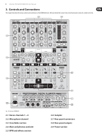
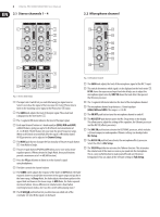
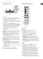
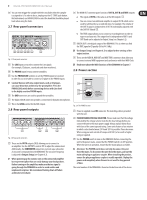
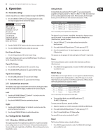
9 DIGITAL PRO MIXER DDM4000 User Manual (66) You can even trigger the sampler with the crossfader when the sampler is assigned to it. To order to do so, simply press the CF START push button. But beforehand, use BANK ASSIGN to select the bank that should be played back when using the fader. 2.7 Rear panel connectors (74) The MAIN OUT connector panel consists of OUT A, OUT B and TAPE outputs: • The signal at OUT A is the same as at the XLR outputs (73). • You can connect an additional amplifier to output OUT B which can be used for a DJ booth or a second club zone, for example. The volume of the OUT B signal is (independent of OUT A) individually adjusted with the OUTPUT B knob (32). • The TAPE output allows you to connect a recording device in order to tape-record your mix. The output level is independent of OUT A and OUT B and can be adjusted in Output Setup (see Chapter 6.2). (75) DIGITAL OUT is the digital output of the DDM4000. This is where you find the TAPE signal in CD quality (16 bit/44.1 kHz). (69) (70) (67) (68) (69) (72) (71) ◊ Use Output Setup (see Chapter 6.2) to adjust further settings of the output section. Fig. 2.7: Rear panel connectors (76) These are the MIDI IN, MIDI OUT and MIDI THRU connectors that allow you to connect external MIDI equipment and synchronize with their MIDI Clock. (67) The LINE inputs are used to connect the Line signals (for example, CD players, soundcards and drum machines). (68) The PHONO inputs let you connect turntables. ◊ Read more about the MIDI functions of the DDM4000 in Chapter 7. 2.9 Power section (69) Use the PHONO/LINE switches to set the PHONO inputs to Line level in order for you to be able to connect a CD player to the PHONO inputs. ◊ Caution! Devices with Line output levels, such as CD players, (79) can cause distortion and destroy the preamplifier. Press the PHONO/LINE switch before connecting devices with Line level to the highly sensitive PHONO inputs. (78) (77) (70) The GND connectors are used to ground the turntables. (71) The balanced XLR connectors provide a connection for dynamic microphones. (72) This is the LEVEL control for the MIC 2 input. Fig. 2.9: The POWER section 2.8 Rear panel outputs (77) Power is supplied via an IEC connector. The matching cable is provided with the unit. (73) (74) (75) (76) Fig. 2.8: Rear panel connectors (73) These are the OUT A outputs (XLR) allowing you to connect to an amplifier. Use the OUTPUT A control (30) to adjust the volume level. Additionally, the SUBWOOFER output lets you hook up a subwoofer. A crossover is integrated into the DDM4000. The crossover frequency is adjusted in Output Setup (see Chapter 6.2). ◊ When powering up the system, turn on the connected amplifier last to prevent spikes that can easily damage your loudspeakers. Before turning on the amplifier, make sure that no signal is going through the DDM4000 in order to avoid sudden and unpleasant surprises. We recommend turning down all faders and knobs beforehand. (78) FUSE RETAINER/VOLTAGE SELECTOR. Please make sure that the voltage indicated by the voltage selector matches the local voltage before you connect the unit to the main power supply. Always replace blown fuses with fuses of the same type and rating. Some units feature a fuse retainer in which a selection between 230 V and 120 V is possible. Please be aware: When using your unit outside of Europe with 120 V, a fuse with a higher rating is required. (79) Use the POWER switch to turn on the DDM4000. Before connecting the unit to the power mains, ensure that the POWER switch is in OFF position. When the unit is in operation, ensure that the mains plug is accessible. ◊ Attention: The POWER switch does not fully disconnect the unit from the mains. To disconnect the unit from the mains, pull out the main cable plug or appliance coupler. When installing the product, ensure the plug or appliance coupler is readily operable. Unplug the power cord completely when the unit is not used for long periods of time. The serial number of the DDM4000 is found on the bottom side of the device.
-
 1
1 -
2
-
3
-
 4
4 -
 5
5 -
 6
6 -
 7
7 -
 8
8 -
 9
9 -
 10
10 -
 11
11 -
 12
12 -
 13
13 -
 14
14 -
15
-
16
-
17
-
18
-
19
-
20
-
21
-
22
-
23
-
24
-
25
-
26
-
27
-
28
-
29
-
30
-
31
-
32
 |
 |
