Behringer EUROCOM SPL3220 Quick Start Guide - Page 6
EUROCOM SPL3220 Controls
 |
View all Behringer EUROCOM SPL3220 manuals
Add to My Manuals
Save this manual to your list of manuals |
Page 6 highlights
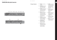
10 EUROCOM SPL3220 EUROCOM SPL3220 Controls (1) (2) (3) (4) (5) (6) (7) (8) (9) (10) 2) (3) (4) (5) (6) (7) (8) (9) (10) (11) (11) (12) 11 Quick Start Guide (EN) Step 2: Controls (12) (1) POWER switch turns the unit (8) LIMITER knob sets the point on and off. by which the output signal (2) THRESHOLD knob determines the level at which the signal will be reduced in dynamics. is not allowed to go beyond. The HI and LO LEDs will light to indicate activity by either limiter. (3) LEVELER knob compensates for varying levels in the program material in order to achieve a consistent compression. (9) METER button determines whether the LEVEL meter displays the input or output level. (4) RATIO knob determines the ratio between the input and output levels for all signals exceeding the threshold point. The control range can be (10) LEVEL meter displays either the input or output level, depending on the position of the METER button. adjusted from 1:1 to 6:1. (11) OUTPUT A and B send the (5) PROGRAM button optimizes the crossover frequency of the processed signal via XLR or Euroblock connectors. two bands for either music (12) INPUT A and B accept signals (500 Hz) or speech (2 kHz). to be processed via XLR, 1/4", (6) GAIN REDUCTION meter or Euroblock connectors. indicates the current gain reduction for each band. (7) OUTPUT knob allows the output signal to be increased or decreased to compensate for level loss due to the compression or limiting.
-
 1
1 -
 2
2 -
 3
3 -
 4
4 -
 5
5 -
 6
6 -
 7
7 -
 8
8 -
 9
9 -
 10
10 -
 11
11 -
 12
12 -
13
-
14
-
15
-
16
-
17
 |
 |
