Behringer SHARK DSP110 Manual - Page 20
Installation
 |
View all Behringer SHARK DSP110 manuals
Add to My Manuals
Save this manual to your list of manuals |
Page 20 highlights
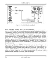
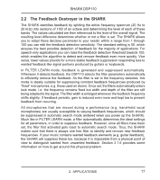
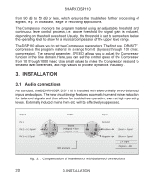
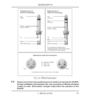
SHARK DSP110 from 90 dB to 50 dB or less, which ensures the troublefree further processing of signals, e.g. in broadcast, stage or recording applications. The Compressor monitors the program material using an adjustable threshold and continuous level control process, i.e. above threshold the signal gain is reduced, depending on threshold overshoot. Usually, the threshold is set to somewhere below the operating level to allow for a musical compression of the upper level range. The DSP110 allows you to set two Compressor parameters. The first one, DENSITY, compresses the program material in a range from 0 (bypass) through 100 (max. compression). The second parameter, SPEED, allows you to adjust the Compressor function in the time domain. Here, you can set the control speed of the Compressor from 10 through 1000 msec. Use small values to make the Compressor respond to smallest level differences, and high values to process dynamics “inaudibly”. 3. INSTALLATION 3.1 Audio connections As standard, the BEHRINGER DSP110 is installed with electronically servo-balanced inputs and outputs. The new circuit design features automatic hum and noise reduction for balanced signals and thus allows for trouble-free operation, even at high operating levels. Externally induced mains hum etc. will be effectively suppressed. Output Pin 1 Pin 2 = (+) Signal Pin 3 = (-) Signal Cable 2 1 3 Shield (+) Signal + Hum (-) Signal + Hum RFI and Hum Input Ground 1 2 Positive 3 Negative (+)Hum + Signal (-)Hum + Signal 2 x Signal = Signal + 6 dB Fig. 3.1: Compensation of interference with balanced connections 20 3. INSTALLATION
-
 1
1 -
2
-
3
-
4
-
5
-
6
-
7
-
8
-
9
-
10
-
11
-
12
-
13
-
14
-
 15
15 -
 16
16 -
 17
17 -
 18
18 -
 19
19 -
 20
20 -
 21
21 -
 22
22 -
 23
23 -
 24
24 -
 25
25 -
26
 |
 |