Behringer SHARK DSP110 Manual - Page 24
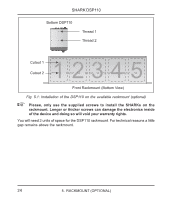
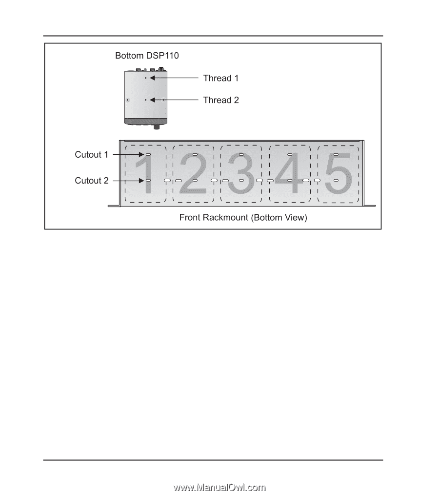
Fig. 5.1: Installation of the DSP110 on the available rackmount optional
 |
View all Behringer SHARK DSP110 manuals
Add to My Manuals
Save this manual to your list of manuals |
Page 24 highlights
SHARK DSP110 Fig. 5.1: Installation of the DSP110 on the available rackmount (optional) + Please, only use the supplied screws to install the SHARKs on the rackmount. Longer or thicker screws can damage the electronics inside of the device and doing so will void your warranty rights. You will need 2 units of space for the DSP110 rackmount. For technical reasons a little gap remains above the rackmount. 24 5. RACKMOUNT (OPTIONAL)
-
 1
1 -
2
-
3
-
4
-
5
-
6
-
7
-
8
-
9
-
10
-
11
-
12
-
13
-
14
-
15
-
16
-
17
-
18
-
 19
19 -
 20
20 -
 21
21 -
 22
22 -
 23
23 -
 24
24 -
 25
25 -
 26
26
 |
 |
24
SHARK DSP110
Fig. 5.1: Installation of the DSP110 on the available rackmount (optional)
+
Please, only use the supplied screws to install the SHARKs on the
rackmount. Longer or thicker screws can damage the electronics inside
of the device and doing so will void your warranty rights.
You will need 2 units of space for the DSP110 rackmount. For technical reasons a little
gap remains above the rackmount.
5.
RACKMOUNT (OPTIONAL)