Biostar NF61S-M2 TE Setup Manual
Biostar NF61S-M2 TE Manual
 |
View all Biostar NF61S-M2 TE manuals
Add to My Manuals
Save this manual to your list of manuals |
Biostar NF61S-M2 TE manual content summary:
- Biostar NF61S-M2 TE | Setup Manual - Page 1
NF61S-M2 TE Setup Manual FCC Information and Copyright This equipment has been tes ted and found to comply with the radio frequency energy and, if not ins talled and used in accordance with the instructions , may cause harmful interference to radio communications . There is no guarantee that - Biostar NF61S-M2 TE | Setup Manual - Page 2
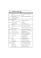
Motherboard Features 2 1.4 Rear Panel Connectors 3 1.5 Motherboard Layout 4 Chapter 2: Hardware Installation 5 2.1 Installing Central Processing Unit (CPU 5 2.2 FAN Headers 7 2.3 Installing System Memory Help 20 5.1 Driver Installation Note 20 5.2 Award BIOS Bee p Code 21 - Biostar NF61S-M2 TE | Setup Manual - Page 3
NF61S-M2 TE CHAPTER 1: INTRODUCTION 1.1 BEFORE YOU START Thank you for wate r. 1.2 PACKAGE CHECKLIST HDD Cable X 1 Rear I/O Panel for ATX Case X 1 Installation Guide X 1 Fully Se tup Drive r C D X 1 (full ve rsion manual files inside ) Se rial ATA Cable X 1 FDD Cable X 1 (optional) Se rial ATA - Biostar NF61S-M2 TE | Setup Manual - Page 4
Motherboard Manual 1.3 MOT HERBOARD FEAT URES SPEC Socket AM2 AMD 64Architecture enables 32 and 64 bit CPU AMDAthlon 64 / Athlon 64FX / Athlon 64 X2 computing / Sempron processors Supports Hyper Transport andCool=n=Quiet Supports up to 1GHz Bandwidth FSB Support HyperTransport Chipset - Biostar NF61S-M2 TE | Setup Manual - Page 5
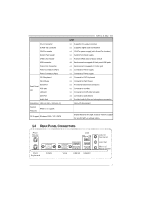
Serial Port Back Panel VGA port I/O LAN port USB Port Audio Jack BoardSize 190 mm (W) x 244 mm (L) Special Features RAID 0 / 1 support OS Support Windows 2000 / XP / VISTA NF61S-M2 TE SPEC x1 Supports CD audio-in function x1 Supports digital audio out function x1 CPU Fan power supply (with - Biostar NF61S-M2 TE | Setup Manual - Page 6
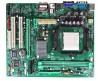
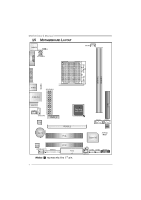
Motherboard Manual 1.5 MOT HERBOARD LAYOUT J KBM S1 J1 JATXPWR2 JCFAN1 JCOM1 Socket A M2 JVGA1 DI MMA1 DI MMB1 JUSB1 J2 JATXPWR1 JUSBLAN1 I DE1 JAUDIO1 JCDIN1 JAUDIOF1 LAN PEX1_1 GeForce 6100-405 PEX16_1 BAT1 PCI1 SATA1 SATA2 BIOS Super I/O JCMOS1 Codec JSPDIF_OUT1 JPRNT1 PCI2 - Biostar NF61S-M2 TE | Setup Manual - Page 7
NF61S-M2 TE CHAPTER 2: HARDWARE INSTALLATION 2.1 INST ALLING CENT RAL PROCESSING UNIT (CPU) Step 1: Remove the socket protection cap. Step 2: Pull the lever toward direction A from the socket and then raise the lever up to a 90-degree angle. Step 3: Look for the white triangle on socket, and the - Biostar NF61S-M2 TE | Setup Manual - Page 8
Motherboard Manual Step 4: Hold the CPU down firmly, and then close the lever toward direct B to complete the installation. Step 5: Put the CPU Fan on the CPU and buckle it. Connect the CPU FAN power cable to the JCFAN1. This completes the installation. 6 - Biostar NF61S-M2 TE | Setup Manual - Page 9
NF61S-M2 TE 2.2 FAN HEADERS These fan headers support cooling-fans built in the computer. The fan cable and connector may be different according to the fan manufacturer. Connect the fan cable to the connector while matching the black wire to pin#1. JC FAN1: C PU Fan Heade r 4 1 Pin Assignment 1 - Biostar NF61S-M2 TE | Setup Manual - Page 10
DIMMA1 DIMMB1 Motherboard Manual 2.3 INST ALLING SYST EM MEMORY A. Memory Modules 1. Unlock a DIMM slot by pressing the retaining clips outward. Align a DIMM on the slot such that the notch on the DIMM matches the break - Biostar NF61S-M2 TE | Setup Manual - Page 11
NF61S-M2 TE B. Memory Capacity DIMM Socket Location DIMMA1 DIMMB1 DDR Module 256MB/512MB/1GB/2GB *1 256MB/512MB/1GB/2GB *1 Total Memory Size Max memory 4GB. C. Dual Channel Memory installation To trigger the Dual Channel f unction of the motherboard, the memory module must meet the following - Biostar NF61S-M2 TE | Setup Manual - Page 12
Motherboard Manual 2.4 CONNECT ORS AND SLOT S FDD1: Floppy Disk Conne ctor The motherboard prov ides a standard floppy disk connector that supports 360K, 720K, 1.2M, 1.44M and 2.88M floppy disk ty pes. This connector supports the prov ided f loppy drive ribbon cables. 2 34 1 33 IDE1: Hard Disk - Biostar NF61S-M2 TE | Setup Manual - Page 13
NF61S-M2 TE PEX1_1: PCI-Expre ss x1 Slot - PCI-Express 1.0a compliant. - Data transf er bandwidth up to 250MB/s per direction; 500MB/s in total. - PCI-Express supports a raw bit-rate of 2.5Gb/s on the data pins. - 2X bandwidth ov er the traditional PCI architecture. PEX16_1: PCI-Express x16 Slot (x8 - Biostar NF61S-M2 TE | Setup Manual - Page 14
Motherboard Manual CHAPTER 3: HEADERS & JUMPERS SETUP 3.1 HOW T O SET UP JUMPERS The Panel Heade r This 16-pin connector includes Power-on, Reset, HDD LED, Power LED, and speaker connection. It allows user to connect the PC case's front panel switch f unctions. PWR_LED On/ Off 9 + + - 16 1 - Biostar NF61S-M2 TE | Setup Manual - Page 15
NF61S-M2 TE JATXPWR1: ATX Powe r Source C onne ctor This connector allows user to connect 24-pin power +12V 11 +12V 12 +3.3V JATXPWR2: ATX Powe r Source C onne ctor By connecting this connector, it will provide +12V to CPU power circuit. 32 4 1 Pin Assignment 1 +12V 2 +12V 3 Ground 4 Ground 13 - Biostar NF61S-M2 TE | Setup Manual - Page 16
SATA interf ace, it satisfies the SATA 2.0 spec and with transfer rate of 3.0Gb/s. 14 7 SATA1 SATA2 Pin Assignment 1 Ground 2 TX+ 3 TX4 Ground 5 RX6 RX+ 7 Ground JAUDIO F1: Front Panel Audio Heade r This header allows user to connect the front audio output cable with the PC f ront panel. 10 - Biostar NF61S-M2 TE | Setup Manual - Page 17
NF61S-M2 TE JCDIN1: CD-RO M Audio-in Connector This connector allows user to connect the audio source f rom the v ariaty dev ices, like CD-ROM, DVD-ROM, PCI sound close 13 J3 13 1 3 Pin 2-3 close Note: In order to support this func tion "Power-On s ys tem via U SB device," "J2/ J3" jumper - Biostar NF61S-M2 TE | Setup Manual - Page 18
on Pi n 2-3. JCMO S1: Cle ar CMOS Heade r By placing the jumper on pin2-3, it allows user to restore the BIOS saf e setting and the CMOS data, please carefully f ollow the procedures to avoid damaging the motherboard. 13 Pin 1-2 Close: Normal Operation (default). 13 13 Pin 2-3 Close: Clear CMOS - Biostar NF61S-M2 TE | Setup Manual - Page 19
NF61S-M2 TE JSPDIF_O UT1: Digital Audio-out Conne ctor This connector allows user to connect the PCI bracket SPDIF output header. 13 Pin Assignment 1 +5V 2 SPDIF_OUT 3 Ground JPRNT1: Printe r Port Connector This header allows you to connector printer on the - Biostar NF61S-M2 TE | Setup Manual - Page 20
Motherboard Manual CHAPTER 4: RAID FUNCTIONS 4.1 OPERAT ION SYST EM Supports Windows XP Home/Prof essional Edition, and Windows 2000 Professional. 4.2 RAID ARRAYS RAID supports orm. Uses: Intended for non-critical data requiring high data throughput, or any env ironment that does not require - Biostar NF61S-M2 TE | Setup Manual - Page 21
NF61S-M2 TE RAID 1: Every read and write is actually carried out in parallel across 2 disk drives in a RAID 1 array system. The mirrored (backup) copy of the data can reside on the same disk or on a second redundant drive in the array. RAID 1 provides a hot-standby copy of data if the active volume - Biostar NF61S-M2 TE | Setup Manual - Page 22
for better system performance. You will see the following window after you insert the CD T he setup guide will auto detect your motherboard and operating system. Note: If this window didn't show up after you ins ert the Driver CD, please use file brows er to locate and execute the file SETUP.EXE - Biostar NF61S-M2 TE | Setup Manual - Page 23
NF61S-M2 TE 5.2 AWARD BIOS BEEP CODE Beep Sound One long beep followed by two short beeps Meaning Video card not found or v ideo card memory bad High-low siren sound CPU overheated System will shut down automatically One Short beep when system boot-up No error found during POST Long beeps - Biostar NF61S-M2 TE | Setup Manual - Page 24
Motherboard Manual 5.4 TROUBLESHOOT ING Probable Solution 1. No power to the system at all 1. Make sure power cable is Power light don't illuminate, f an securely plugged in. inside power supply does not turn 2. Replace cable. on. 3. Contact technical support. 2. Indicator light on key - Biostar NF61S-M2 TE | Setup Manual - Page 25
about BIOS model and chipsets. In addition, the frequency status of CPU, memory, VGA and PCI along with the CPU speed Support: Windows 98 SE, Windows Me, Windows 2000, Windows XP, Windows Vista DirectX: DirectX 8.1 or above. (The Windows XP operating system includes DirectX 8.1. If you use Windows XP - Biostar NF61S-M2 TE | Setup Manual - Page 26
Motherboard Manual 6.3 INST ALLAT ION 1. Execute the setup execution file, and then the following dialog will pop up. Please . Click "Finish" button. Usage : The following figures are only for reference, the screen printed in this user manual will change according to your motherboard on hand. 24 - Biostar NF61S-M2 TE | Setup Manual - Page 27
6.4 WARPSPEEDER™ III NF61S-M2 TE 1. Desktop Icon After the [WarpSpeeder™ III] has been window you will see is Main Panel. Main Panel contains fe ature s as follows: a. Display the CPU Speed, CPU external clock, Memory clock, VGA clock, and PCI clock information. b. Contains About, Voltage/Overclock - Biostar NF61S-M2 TE | Setup Manual - Page 28
Motherboard Manual 3. Overcl ock/Overvol tage Panel Click the Overclock/Overvoltage button in the Main Panel, the button will be highlighted and the Overclock/Overvoltage Panel will show up as the following figure. As you can see, the Overclock Panel is on the right side, and the Overvoltage Panel - Biostar NF61S-M2 TE | Setup Manual - Page 29
NF61S-M2 TE O ve rclock Panel contains these fe atures: a. "Auto-Overclock": User can click this button and [WarpSpeeder verified best and stable frequency. b. "Verify": If you use the "Manual Adjust" bar to adjust the CPU frequency, then you can click this button and [WarpSpeeder™ III] will proceed - Biostar NF61S-M2 TE | Setup Manual - Page 30
Motherboard Manual O ve rvoltage Panel contains these fe ature s: a. "CPU Voltage": This function allows user to adjust CPU voltage. Click on "+" to increase or "-" to decrease the CPU voltage. b. "Memory Voltage": This function allows user to adjust Memory voltage. Click on "+" to increase or "-" - Biostar NF61S-M2 TE | Setup Manual - Page 31
NF61S-M2 TE 5. About Panel Click the "about" button in Main Panel, the button will be highlighted and the About Panel will show up as the following figure. In this panel, you can get model name and detail information in hints of all the chipset that are related to overclocking. You can also get the - Biostar NF61S-M2 TE | Setup Manual - Page 32
Motherboard Manual APPENDENCIES: SPEC IN OTHER LANGUAGE GERMAN Spezifikationen Sockel AM2 Die AMD 64-Architektur unterstützt eine 32-Bit- CPU AMDAthlon 64 / SATA-SpezifikationVersion 2.0. LAN Realtek 8201CL PHY 10 / 100 Mb/s Auto-Negotiation Halb-/ Vollduplex-Funktion Audio-Code ALC662 c - Biostar NF61S-M2 TE | Setup Manual - Page 33
PS/2-Maus Serieller Anschluss RückseitenVGA-Anschluss E/A LAN-Anschluss USB-Anschluss Audioanschluss Platinengrö 190 mm (B) X 244mm (L) ße. Sonderfunk Unterstützt RAID 0 / 1 tionen OS-Unterst Windows 2000 / XP / VISTA ützung NF61S-M2 TE Spezifikationen x1 Unterstützt die Fronttafelfunktionen x1 - Biostar NF61S-M2 TE | Setup Manual - Page 34
Motherboard Manual FRANCE SPEC Socket AM2 L'architecture AMD 64 permet le calcul 32 et 64 bits UC Mo IDE Contrôleur IDEintégré SATA II ContrôleurSerial ATA intégré : LAN Realtek 8201CL PHY Codec audio ALC662 Fentes Fente PCI Slot PCI Express x16 Slot PCI Express x 1 Connecteur - Biostar NF61S-M2 TE | Setup Manual - Page 35
x1 E/S du Port série x1 panneau Port VGA x1 arrière Port LAN x1 Port USB x4 Fiche audio x3 Dimensions 190 mm (l) X 244mm (H) de la carte Fonctionnali tés Prise encharge RAID 0 / 1 spéciales Support SE Windows 2000 / XP / VISTA Biostar se réserve le droit d'ajouter ou de supprimer - Biostar NF61S-M2 TE | Setup Manual - Page 36
Motherboard Manual IT ALIAN SPECIFICA CPU Socket AM2 L'architettura AMD 64 abilita l a computazione Processori AMD Athlon 64 / 2.0. LAN Realtek 8201CL PHY Negoziazione automatica 10 / 100 Mb/s Capacità Half / Full Duplex Codec audio ALC662 Uscita audio 5.1 ca nali Supporto audio High- - Biostar NF61S-M2 TE | Setup Manual - Page 37
x1 Porta seriale x1 I/O pannello Porta VGA x1 posteriore Porta LAN x1 Porta USB x4 Connettore audio x3 Dimensioni scheda 190 mm (lar ghezza) x 244 mm (altezza) Caratteristich Supporto RAID 0 / 1 e speciali Sistemi operativi Windows 2000 / XP / VISTA Biostar si riserva il diritto di - Biostar NF61S-M2 TE | Setup Manual - Page 38
Motherboard Manual SPANISH Especificación CPU Conector AM2 La arquitectura AMD 64 permite el procesado de 32 y 64 bits Procesadores AMD Athlon 64 / Athlon 64FX / Athlon 64 X2 / Sempron Soporta las tecnologías - Biostar NF61S-M2 TE | Setup Manual - Page 39
de ventilador de CPU (con X1 funciónSmart Fan) X1 Fuente de alimentación de ventilador de sistema X1 X2 Cada conector soporta 2 puertos USB frontales X1 Cada conector soporta 1 Puerto de impresora X1 X1 X1 X1 X1 X1 X1 X4 X3 Soporte de sistema Windows 2000 / XP / VISTA operativo Biostar se reserva - Biostar NF61S-M2 TE | Setup Manual - Page 40
Motherboard Manual PORT UGUESE ESPECIFICAÇÕES CPU A arquitectura AMD 64 permite uma computação de Socket AM2 32 e 64 bits Processadores ão de dados até 3 Gb/s. Compatibilidade com a especificação SATA versão 2.0. LAN Realtek 8201CL PHY Auto negociação de 10 / 100Mb/s Capacidade semi/full - Biostar NF61S-M2 TE | Setup Manual - Page 41
PS/2 Entradas/S Porta série aídas no Porta VGA painel traseiro Porta LAN Porta USB Tomada de áudio Tamanho 190 mm (L) X 244mm (A) da placa Característi cas Suporta as funções RAID 0 / 1 especiais Sistemas operativos Windows 2000 / XP / VISTA suportados x1 Para suporte de várias fun - Biostar NF61S-M2 TE | Setup Manual - Page 42
Motherboard Manual POLISH SPEC Socket AM2 Architektura AMD 64 umożliwia przetwarzanie 32i Procesor AMDAthlon 64 / Athlon 64 FX / Athlon 64X2 64 bitowe / Sempron Procesory Obsługa Hyper Transport oraz Cool'n'Quiet Obsługa HyperTransport o szerokości pasma FSB do1 GHz Chipset LAN cie audio Obs - Biostar NF61S-M2 TE | Setup Manual - Page 43
PS/2 Back Panel I/O Port szeregowy Port VGA Port LAN Port USB Gniazdo audio Wymiary płyty 190 mm (S) X 244 mm (W) Funkcje specjalne Obsługa RAID 0 / 1 O bs luga systemu Windows 2000 / XP / VISTA operacyjne go NF61S-M2 TE SPEC x1 Obsługa funkcji wejścia audio CD x1 Obsługa funkcji cyfrowego - Biostar NF61S-M2 TE | Setup Manual - Page 44
Motherboard Manual RUSSIAN СПЕЦ CPU AM2 AMD 64 AMDAthlon 64 / Athlon 64 FX 32 и 64 бит Athlon 64 X2 / Sempron Hyper Transport иCool'n'Quiet HyperTransport FSB 1GГц GeForce 6100-405 Слоты - Biostar NF61S-M2 TE | Setup Manual - Page 45
x1 CMOS x1 USB 2 USB-порта x2 1 Порт x1 24 вывод) x1 4 вывод) x1 PS/2 x1 Мышь PS/2 x1 x1 Порт VGA x1 LAN x1 USB-порт x4 x3 190 мм (Ш) X 244 мм (В) RAID 0/ 1 Biostar OS Windows 2000 / XP / VISTA OS с 43 - Biostar NF61S-M2 TE | Setup Manual - Page 46
Motherboard Manual ARABIC 32و 64ﺏﺖAMD 64 Cool'n'QuietوHyper Transport AM2 AMD Athlon 64 / Athlon 64FX Athlon 64 X2 / Sempron 1000 HyperTransport GeForce 6100-405 DDR2 800 / 667 / 533 /400 DDR2 ECC DIMM 2 DDR2 DIMM DDR2 - Biostar NF61S-M2 TE | Setup Manual - Page 47
1 1 1 2 USB 1 1 1 1 1 1 1 1 4 3 Biostar NF61S-M2 TE SATA CD-IN S/PDIF CMOS USB 24 4 PS/2 PS/2 VGA USB RAID 0 / 1 190 244 X Windows 2000 / XP / VISTA 45 - Biostar NF61S-M2 TE | Setup Manual - Page 48
Motherboard Manual JAPANESE 仕様 CPU AMD 64 32ビットと64 Socket AM2 AMDAthlon 64 / Athlon 64 FX / Athlon 64X2 / Sempron 1 GHz 66 / 100 / 133 PIO Mode 0~4 SATA II ATA 最高3 Gb SATA 2.0 LAN Realtek 8201CL PHY 10 / 100 Mb Codec ALC662 5.1 PCIスロット x2 PCI Express x16スロット - Biostar NF61S-M2 TE | Setup Manual - Page 49
24ピン) 4ピン) PS/2 PS/2マウス I/O VGAポート LANポート USBポート 190 mm (幅) X 244 mm (高さ) RAID 0 / 1 OS Windows 2000 / XP / VISTA NF61S-M2 TE 仕様 x2 1つのSATA x1 x1 x1 CD x1 x1 CPU x1 x1 2 USB x2 します x1 1 x1 x1 x1 x1 x1 x1 x1 x4 x3 Biostar OS 2008/02/21 47
-
 1
1 -
 2
2 -
 3
3 -
 4
4 -
 5
5 -
 6
6 -
 7
7 -
8
-
9
-
10
-
11
-
12
-
13
-
14
-
15
-
16
-
17
-
18
-
19
-
20
-
21
-
22
-
23
-
24
-
25
-
26
-
27
-
28
-
29
-
30
-
31
-
32
-
33
-
34
-
35
-
36
-
37
-
38
-
39
-
40
-
41
-
42
-
43
-
44
-
45
-
46
-
47
-
48
-
49
 |
 |

NF61S-M2 TE Setup Manual
FCC Information and Copyright
This equipment has been tested and found to comply with the limits of a Class
B digital device, pursuant to Part 15 of the FCC Rules. These limits are designed
to provide reasonable protection against harmful interference in a residential
installation. This equipment generates, uses, and can radiate radio frequency
energy and, if not installed and used in accordance with the instructions, may
cause harmful interference to radio communications. There is no guarantee
that interference will not occur in a particular installation.
The vendor makes no representations or warranties with respect to the
contents here and specially disclaims any implied warranties of merchantability
or fitness for any purpose. Further the vendor reserves the right to revise this
publication and to make changes to the contents here without obligation to
notify any party beforehand.
Duplication of this publication, in part or in whole, is not allowed without first
obtaining the vendor’s approval in writing.
The content of this user’s manual is subject to be changed without notice and
we will not be responsible for any mistakes found in this user’s manual. All the
brand and product names are trademarks of their respective companies.