Biostar NF61S-M2 TE Setup Manual - Page 14
Headers & Jumpers Setup
 |
View all Biostar NF61S-M2 TE manuals
Add to My Manuals
Save this manual to your list of manuals |
Page 14 highlights
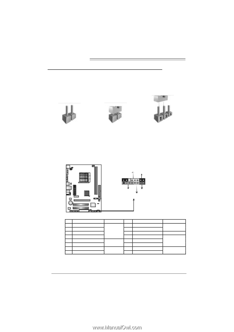
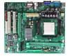
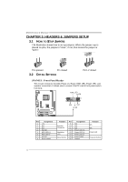
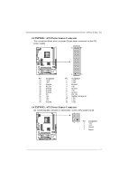
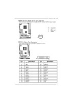
Motherboard Manual CHAPTER 3: HEADERS & JUMPERS SETUP 3.1 HOW T O SET UP JUMPERS The illustration shows how to set up jumpers. When the jumper cap is placed on pins, the jumper is "close", if not, that means the jumper is "open". Pin opened Pin closed 3.2 DET AIL SETT INGS Pin1-2 closed JPANEL1: Front Panel Heade r This 16-pin connector includes Power-on, Reset, HDD LED, Power LED, and speaker connection. It allows user to connect the PC case's front panel switch f unctions. PWR_LED On/ Off 9 + + - 16 1 +- 8 SPK RST HL ED Pin Assignment 1 +5V 2 N/A 3 N/A 4 Speaker 5 HDD LED (+) 6 HDD LED (-) 7 Ground 8 Reset control Functio n Pin 9 Speaker 10 Connec tor 11 12 Hard drive 13 LED 14 Reset button 15 16 Assignment N/A N/A N/A Power LED (+) Power LED (+) Power LED (-) Power button Ground Functio n N/A N/A Power LED Power-on button 12
-
 1
1 -
2
-
3
-
4
-
5
-
6
-
7
-
8
-
 9
9 -
 10
10 -
 11
11 -
 12
12 -
 13
13 -
 14
14 -
 15
15 -
 16
16 -
 17
17 -
 18
18 -
 19
19 -
20
-
21
-
22
-
23
-
24
-
25
-
26
-
27
-
28
-
29
-
30
-
31
-
32
-
33
-
34
-
35
-
36
-
37
-
38
-
39
-
40
-
41
-
42
-
43
-
44
-
45
-
46
-
47
-
48
-
49
 |
 |