Bosch 1775E Operating Instructions - Page 9
Operating Instructions - brush
 |
UPC - 000346324228
View all Bosch 1775E manuals
Add to My Manuals
Save this manual to your list of manuals |
Page 9 highlights
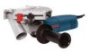
BM 3609929818 3/03 3/10/03 8:42 AM Page 9 Operating Instructions SLIDE ON-OFF SWITCH WITH LOCK The tool is switched "ON" by the switch button located at the side of the motor housing. The switch can be locked in the "ON" position, a convenience for long grinding operations. TO TURN THE TOOL "ON" without locking it, slide the switch button forward by applying pressure ONLY at the REAR portion of the button. When pressure is released the switch button will snap to "OFF" position. TO LOCK THE SWITCH "ON", slide the switch button forward and press "IN" the FRONT portion. TO UNLOCK THE SWITCH, simply press and release the REAR portion of the button. Switch is spring loaded and will snap back automatically. ! WARNING Hold the tool with both hands while starting the tool, since torque from the motor can cause the tool to twist. Start the tool before applying to work and let the tool come to full speed before contacting the workpiece. Lift the tool from the work before releasing the switch. DO NOT turn the switch "ON" and "OFF" while the tool is under load; this will greatly decrease the switch life. CONSTANT RESPONSE CIRCUITRY The internal electronic feedback system provides a "soft start", which will reduce the stresses that occur from a high torque start. The system also helps to keep the no load speed virtually constant between no-load and load conditions. OVERLOAD PROTECTION Your tool is equipped with overload protection to protect the motor. If the tool stops during operation TURN OFF SWITCH IMMEDIATELY and allow the motor to cool for about 30 seconds by running at no-load. If the overload protection stops the tool repeatedly, excessive force is causing the tool to overload. Don't press so hard and let the tool do the work. SERVICE MINDER™ BRUSHES Eliminates quess work, stops the tool when preventive maintenance is required. ADJUSTABLE DEPTH STOP Your tool is equipped with an adjustable stop. Your cutting depth can be pre-set and/or repeated by using the depth stop (Fig. 1). 1. Loosen the depth stop lock knob. 2. Depress stop button, move to desired position on depth bracket, and release button to secure stop in place. 3. Place foot against workpiece, push down on tool until it stops. 4. To secure and hold foot and guard assembly at desired depth of cut. Move foot to desired depth of cut and securely tighten the depth stop lock knob. WHEEL GUARD ! WARNING Wheel guard must be attached when using abrasive wheels. Always keep wheel guard between you and your work while grinding. Position the wheel guard such that the dust port does not interfere with the On/Off switch. To adjust guard, loosen clamp screw and rotate guard to desired position, and securely tighten screw. Always keep the wheel guard between you and your work when during operation. DUST EXTRACTION ! WARNING This tool must only be used with a dust extraction system. In addition, always wear approved dust mask. Your tool is equipped with a dust port for dust extraction. To use this feature, insert adapter into dust port (Fig. 2), then insert vacuum hose (optional accessory) into the adapter and connect the opposite end of the hose to a shop vacuum cleaner. Always make sure the vacuum cleaner that you use is designed for extraction of masonry dust. AUXILIARY HANDLE The auxiliary handle, used to guide and balance the tool can be bolted to either side of the spindle housing depending on personal preference and comfort. Always use the auxiliary handle for maximum control and ease of operation. -9-
-
 1
1 -
2
-
3
-
 4
4 -
 5
5 -
 6
6 -
 7
7 -
 8
8 -
 9
9 -
 10
10 -
 11
11 -
 12
12 -
 13
13 -
 14
14 -
15
-
16
-
17
-
18
-
19
-
20
-
21
-
22
-
23
-
24
-
25
-
26
-
27
-
28
-
29
-
30
-
31
-
32
 |
 |
