Bose Acoustimass 16 Series II Owner's guide - Page 9
Connecting the Acoustimass, module to the receiver - he wiring
 |
View all Bose Acoustimass 16 Series II manuals
Add to My Manuals
Save this manual to your list of manuals |
Page 9 highlights
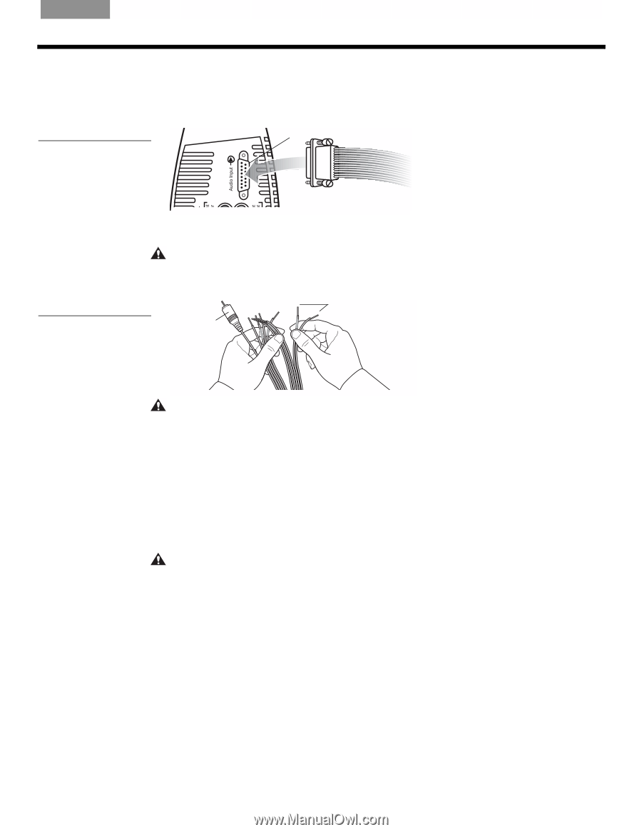
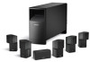
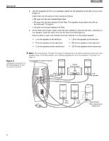
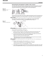
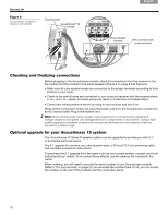
English Español Français SETTING UP Figure 6 System input cable connectors Connecting the Acoustimass® module to the receiver The system input cable is 20 feet (6.1 meter) long and connects the Acoustimass module to your surround sound receiver. Unlike the speaker cables, this input cable has a multi-pin ! connector that inserts into the Audio Input jack on the module (Figure 6). Module input jack Figure 7 Unzipping the paired wires System input cable connector At the other end of the system input cable, multiple wire pairs that "unzip" for easy reach and insertion into terminals on your receiver (Figure 7). A red collar marks a wire as positive (+). CAUTION: Do NOT connect your module to the TV, which lacks the required amplification. The single RCA connector at that end is for use ONLY with a receiver that handles ! low-frequency effects and provides an LFE/SUBWOOFER jack (Figure 7). Wire pair RCA connector for LFE only CAUTION: Before making these connections, turn off your receiver to prevent unwanted noises when you plug the Acoustimass® module into it. To make the connections (Figure 8 on page 10): 1. Insert the multi-pin connector on the system input cable into the input jack on the ! Acoustimass module. Tighten the two thumbscrews to secure the connection. 2. Connect each wire pair on the other end of the system input cable to your surround receiver, which should have audio output terminals labeled: • Right, Left, Center for the front audio channels • Right Surround, Left Surround, and possibly Center Surround for the rear channels. ! The specific labels on your receiver may differ slightly. CAUTION: Do not allow exposed wires to brush against each other; this could damage your receiver. 3. Carefully match the polarity of the connections (+ to + and - to -). • Attach each red-collared wire (+) to the appropriate + terminal. • Attach each plain wire (-) to the appropriate - terminal. 4. If applicable to your receiver, insert the RCA plug marked LFE on the system input cable into the LFE/SUBWOOFER OUT jack on your surround receiver. Remove the cover first. 9
-
 1
1 -
2
-
3
-
 4
4 -
 5
5 -
 6
6 -
 7
7 -
 8
8 -
 9
9 -
 10
10 -
 11
11 -
 12
12 -
 13
13 -
 14
14 -
15
-
16
-
17
-
18
-
19
-
20
-
21
-
22
-
23
-
24
-
25
-
26
-
27
-
28
-
29
-
30
-
31
-
32
-
33
-
34
-
35
-
36
-
37
-
38
-
39
-
40
-
41
-
42
-
43
-
44
 |
 |