Cisco ESW-520-48P-K9 Software Guide - Page 118
Example 12-7 Viewing ATM Packet Processing, Software Upgrade Methods
 |
View all Cisco ESW-520-48P-K9 manuals
Add to My Manuals
Save this manual to your list of manuals |
Page 118 highlights
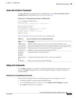
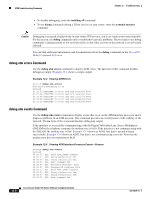
Software Upgrade Methods Chapter 12 Troubleshooting Example 12-7 shows sample output for the debug atm packet command. Example 12-7 Viewing ATM Packet Processing Router# debug atm packet Router# 01:23:48:ATM0(O): VCD:0x1 VPI:0x1 VCI:0x64 DM:0x0 SAP:AAAA CTL:03 OUI:000000 TYPE:0800 Length:0x70 01:23:48:4500 0064 0008 0000 FF01 9F80 0E00 0010 0E00 0001 0800 A103 0AF3 17F7 0000 01:23:48:0000 004C BA10 ABCD ABCD ABCD ABCD ABCD ABCD ABCD ABCD ABCD ABCD ABCD ABCD 01:23:48:ABCD ABCD ABCD ABCD ABCD ABCD ABCD ABCD ABCD ABCD ABCD ABCD ABCD ABCD ABCD 01:23:48:ABCD ABCD ABCD ABCD ABCD 01:23:48: 01:23:48:ATM0(I): VCD:0x1 VPI:0x1 VCI:0x64 Type:0x0 SAP:AAAA CTL:03 OUI:000000 TYPE:0800 Length:0x70 01:23:48:4500 0064 0008 0000 FE01 A080 0E00 0001 0E00 0010 0000 A903 0AF3 17F7 0000 01:23:48:0000 004C BA10 ABCD ABCD ABCD ABCD ABCD ABCD ABCD ABCD ABCD ABCD ABCD ABCD 01:23:48:ABCD ABCD ABCD ABCD ABCD ABCD ABCD ABCD ABCD ABCD ABCD ABCD ABCD ABCD ABCD 01:23:48:ABCD ABCD ABCD ABCD ABCD 01:23:48: Table 12-3 describes some of the fields shown in the debug atm packet command output. Table 12-3 debug atm packet Command Output Description Field ATM0 (O) VCD: 0xn VPI: 0xn DM: 0xn Length: n Description Interface that is generating the packet. Output packet. (I) would mean receive packet. Virtual circuit associated with this packet, where n is some value. Virtual path identifier for this packet, where n is some value. Descriptor mode bits, where n is some value. Total length of the packet (in bytes) including the ATM headers. Software Upgrade Methods Several methods are available for upgrading software on the Cisco Secure Router 520 Series routers, including: • Copy the new software image to flash memory over the LAN or WAN while the existing Cisco IOS software image is operating. • Copy the new software image to flash memory over the LAN while the boot image (ROM monitor) is operating. • Copy the new software image over the console port while in ROM monitor mode. • From ROM monitor mode, boot the router from a software image that is loaded on a TFTP server. To use this method, the TFTP server must be on the same LAN as the router. 12-8 Cisco Secure Router 520 Series Software Configuration Guide OL-14210-01
-
 1
1 -
2
-
3
-
4
-
5
-
6
-
7
-
8
-
9
-
10
-
11
-
12
-
13
-
14
-
15
-
16
-
17
-
18
-
19
-
20
-
21
-
22
-
23
-
24
-
25
-
26
-
27
-
28
-
29
-
30
-
31
-
32
-
33
-
34
-
35
-
36
-
37
-
38
-
39
-
40
-
41
-
42
-
43
-
44
-
45
-
46
-
47
-
48
-
49
-
50
-
51
-
52
-
53
-
54
-
55
-
56
-
57
-
58
-
59
-
60
-
61
-
62
-
63
-
64
-
65
-
66
-
67
-
68
-
69
-
70
-
71
-
72
-
73
-
74
-
75
-
76
-
77
-
78
-
79
-
80
-
81
-
82
-
83
-
84
-
85
-
86
-
87
-
88
-
89
-
90
-
91
-
92
-
93
-
94
-
95
-
96
-
97
-
98
-
99
-
100
-
101
-
102
-
103
-
104
-
105
-
106
-
107
-
108
-
109
-
110
-
111
-
112
-
 113
113 -
 114
114 -
 115
115 -
 116
116 -
 117
117 -
 118
118 -
 119
119 -
 120
120 -
 121
121 -
 122
122 -
 123
123 -
124
-
125
-
126
-
127
-
128
-
129
-
130
-
131
-
132
-
133
-
134
-
135
-
136
-
137
-
138
-
139
-
140
-
141
-
142
-
143
-
144
-
145
-
146
-
147
-
148
-
149
-
150
-
151
-
152
-
153
-
154
-
155
-
156
-
157
-
158
-
159
-
160
-
161
-
162
 |
 |
