Cisco VG202 Hardware Installation Guide
Cisco VG202 Manual
 |
View all Cisco VG202 manuals
Add to My Manuals
Save this manual to your list of manuals |
Cisco VG202 manual content summary:
- Cisco VG202 | Hardware Installation Guide - Page 1
Cisco VG202 and Cisco VG204 Voice Gateways Hardware Installation Guide Americas Headquarters Cisco Systems, Inc. 170 West Tasman Drive San Jose, CA 95134-1706 USA http://www.cisco.com Tel: 408 526-4000 800 553-NETS (6387) Fax: 408 527-0883 Text Part Number: OL-15959-01 - Cisco VG202 | Hardware Installation Guide - Page 2
. CCDE, CCENT, Cisco Eos, Cisco Lumin, Cisco Nexus, Cisco StadiumVision, Cisco TelePresence, Cisco WebEx, the Cisco logo, DCE, and Welcome to the Human Network are trademarks; Changing the Way We Work, Live, Play, and Learn and Cisco Store are service marks; and Access Registrar, Aironet, AsyncOS - Cisco VG202 | Hardware Installation Guide - Page 3
Cisco VG202 and Cisco VG204 Voice Gateways Hardware Installation Guide Copyright © 2008 Cisco Systems, Inc. All rights reserved. - Cisco VG202 | Hardware Installation Guide - Page 4
- Cisco VG202 | Hardware Installation Guide - Page 5
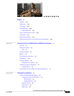
Grounding 1-5 Memory 1-5 Port Numbering Conventions 1-6 Specifications 1-6 Software Elements 1-6 Configuration Connections 1-6 Interfaces and Service Capabilities 1-7 Interface Options 1-7 Cisco VG202 and Cisco VG204 Voice Gateway Deployment 1-7 Planning Your Installation 2-1 Location and Mounting - Cisco VG202 | Hardware Installation Guide - Page 6
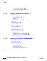
Checklist for Power-On 4-1 Power-On Procedure 4-1 Initial Configuration Procedures 4-2 Cisco IOS CLI 4-2 Setup Command Facility 4-3 Manual Configuration 4-6 Verifying and Saving Your Configuration 4-6 Troubleshooting 4-6 Cisco VG202 and Cisco VG204 Voice Gateways Hardware Installation Guide vi OL - Cisco VG202 | Hardware Installation Guide - Page 7
considerations. Instructions for installing the Cisco VG202 and Cisco VG204 voice gateways and connecting the cables. Powering up the Cisco VG202 and Cisco VG204 voice gateways and preparing for configuration. OL-15959-01 Cisco VG202 and Cisco VG204 Voice Gateways Hardware Installation Guide vii - Cisco VG202 | Hardware Installation Guide - Page 8
passwords, appear in angle brackets in contexts where italic font is not available. Default help you solve a problem. The tips information might not be troubleshooting or even an action Cisco VG202 and Cisco VG204 Voice Gateways. Cisco VG202 and Cisco VG204 Voice Gateways Hardware Installation Guide - Cisco VG202 | Hardware Installation Guide - Page 9
that accompanied this device. Statement 1071 SAVE THESE INSTRUCTIONS Waarschuwing BELANGRIJKE VEILIGHEIDSINSTRUCTIES Dit waarschuwingssymbool betekent gevaar. U BEWAHREN SIE DIESE SICHERHEITSANWEISUNGEN AUF OL-15959-01 Cisco VG202 and Cisco VG204 Voice Gateways Hardware Installation Guide ix - Cisco VG202 | Hardware Installation Guide - Page 10
olyckor. Se översättningarna av de varningsmeddelanden som finns i denna publikation, och se de översatta säkerhetsvarningarna som medföljer denna anordning. OBS! SPARA DESSA ANVISNINGAR Cisco VG202 and Cisco VG204 Voice Gateways Hardware Installation Guide x OL-15959-01 - Cisco VG202 | Hardware Installation Guide - Page 11
Preface Safety Warnings OL-15959-01 Cisco VG202 and Cisco VG204 Voice Gateways Hardware Installation Guide xi - Cisco VG202 | Hardware Installation Guide - Page 12
åelse af ulykker. Brug erklæringsnummeret efter hver advarsel for at finde oversættelsen i de oversatte advarsler, der fulgte med denne enhed. GEM DISSE ANVISNINGER Cisco VG202 and Cisco VG204 Voice Gateways Hardware Installation Guide xii OL-15959-01 - Cisco VG202 | Hardware Installation Guide - Page 13
Preface Safety Warnings OL-15959-01 Cisco VG202 and Cisco VG204 Voice Gateways Hardware Installation Guide xiii - Cisco VG202 | Hardware Installation Guide - Page 14
on the bottom of the chassis, near the compliance label. The size of the serial number label is 0.25 x 1 inch (0.635 x 2.54 centimeters). It has the letters "SN:" followed by eleven characters. (See Figure 0-1.) Cisco VG202 and Cisco VG204 Voice Gateways Hardware Installation Guide xiv OL-15959-01 - Cisco VG202 | Hardware Installation Guide - Page 15
Preface Accessibility Figure 0-1 Serial Number Location on Cisco VG202 and Cisco VG204 Voice Gateways Cisco 11 character label SN: AAANNNNXXXX 188241, 781-00608-01 Accessibility These voice gateways can be configured by using the Cisco command-line interface (CLI). The CLI conforms to code 508 - Cisco VG202 | Hardware Installation Guide - Page 16
Cisco Product Document Title Cisco VG202 and Cisco • Cisco VG202 and Cisco VG204 Voice Gateways Hardware Installation Guide (this book) VG204 voice gateways • Cisco VG202 and Cisco VG204 Voice Gateways Quick Start Guide • Cisco VG202 and Cisco VG204 Voice Gateways Software Configuration Guide - Cisco VG202 | Hardware Installation Guide - Page 17
analog phones, fax machines, and modems. The Cisco VG202 and Cisco VG204 voice gateways provide support for 2-FXS (Cisco VG202) and 4-FXS (Cisco VG204) ports and parity with Cisco IOS fax/modem, security, and Session Initiation Protocol (SIP) features. Both voice gateways are configurable with Cisco - Cisco VG202 | Hardware Installation Guide - Page 18
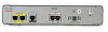
Figure 1-3 shows the interfaces and ports on the Cisco VG202 voice gateway. Figure 1-4 shows the interfaces and ports on the Cisco VG204 voice gateway. All interface ports are on the back of the chassis. Cisco VG202 and Cisco VG204 Voice Gateways Hardware Installation Guide 1-2 OL-15959-01 - Cisco VG202 | Hardware Installation Guide - Page 19
of the Cisco VG202 and Cisco VG204 Voice Gateways Figure 1-3 Cisco VG202 Voice Gateway Chassis Physical Description 231880 FastEthernet CONSOLE VG202 FXS 0/1 0/0 AUX 12 0/1 0/0 12V DC SA 3 4 5 6 1 Fast Ethernet port 1, Fast Ethernet port 0 4 Power connector 2 Serial port-console - Cisco VG202 | Hardware Installation Guide - Page 20
ports 0 through 3-green 3 FE ports 0/1-green Description Off-no power Steady on-normal operation Slow blink-bootup phase or in ROMMON monitor mode Off-On hook Steady On-Off hook Off-No link Steady on-link Blinking-TXD/RXD data Cisco VG202 and Cisco VG204 Voice Gateways Hardware Installation Guide - Cisco VG202 | Hardware Installation Guide - Page 21
Warning Ultimate disposal of this product should be handled according to all national laws and regulations. Statement 1040 Memory The Cisco VG202 and VG204 voice gateways contain flash memory and main memory. OL-15959-01 Cisco VG202 and Cisco VG204 Voice Gateways Hardware Installation Guide 1-5 - Cisco VG202 | Hardware Installation Guide - Page 22
VG202 or Cisco VG204 voice gateway. The configuration can be performed in several ways: • Locally, with a direct connection through the serial port • Remotely, with a connection through the serial port • Through Telnet and TFTP Cisco VG202 and Cisco VG204 Voice Gateways Hardware Installation Guide - Cisco VG202 | Hardware Installation Guide - Page 23
10/100BASE-T (802.3) Ports 0/0, 0/1 LAN Ports 0 to 2, or FXS (loop-start or 0 to 4 ground-start) Analog phone, fax, or modem Services Supported Local administrative access Data Analog voice/fax or modem Details RJ-45 physical interface RJ-45 physical interface 2-port FXS, on premises only - Cisco VG202 | Hardware Installation Guide - Page 24
CONSOLE AUX VG204 FXS 0/3 0/2 0/1 0/0 12V DC SA 4 3 1 Fast Ethernet port Fast Ethernet straight-through cable 3 connected to an Ethernet hub 2 Console port RJ-45-to-DB9 console cable connected to 4 a PC Cisco VG202 and Cisco VG204 Voice Gateways Hardware Installation Guide 1-8 OL-15959-01 - Cisco VG202 | Hardware Installation Guide - Page 25
chassis • Access to a suitable power source • Access to an appropriate earth ground • Allowance for adequate heat dissipation and airflow around the chassis Temperature Control and Ventilation The installation area (room, closet, or cabinet) for the Cisco VG202 and Cisco VG204 voice gateways should - Cisco VG202 | Hardware Installation Guide - Page 26
Maximum Distance, page 2-2 • FXS Analog Voice Port Maximum Distance, page 2-3 Fast Ethernet Maximum Distance The maximum segment distance for Fast Ethernet is 330 feet (100 meters) (specified in IEEE 802.3). Cisco VG202 and Cisco VG204 Voice Gateways Hardware Installation Guide 2-2 OL-15959-01 - Cisco VG202 | Hardware Installation Guide - Page 27
Installation Interference Considerations FXS Analog Voice Port Maximum Distance The maximum distance is established by a total allowable loop resistance, including the phone radio-frequency interference (RFI). OL-15959-01 Cisco VG202 and Cisco VG204 Voice Gateways Hardware Installation Guide 2-3 - Cisco VG202 | Hardware Installation Guide - Page 28
Interference Considerations Chapter 2 Planning Your Installation Cisco VG202 and Cisco VG204 Voice Gateways Hardware Installation Guide 2-4 OL-15959-01 - Cisco VG202 | Hardware Installation Guide - Page 29
section on page 3-3. Warning Read the installation instructions before connecting the system to the power source. Statement 1004 Safety Recommendations The when working on equipment powered by electricity. OL-15959-01 Cisco VG202 and Cisco VG204 Voice Gateways Hardware Installation Guide 3-1 - Cisco VG202 | Hardware Installation Guide - Page 30
Installing Cisco VG202 and Cisco VG204 Voice Gateways Warning Do not work on the system or connect or disconnect cables during periods of lightning activity. Statement 1001 Warning This equipment must be installed and maintained by service victim yourself. - Turn off power to the system. - If - Cisco VG202 | Hardware Installation Guide - Page 31
Checklist Installation Checklist for site Cisco VG name/serial number Task Background information placed in Site Log Environmental specifications verified Site power voltages verified Verified by Date OL-15959-01 Cisco VG202 and Cisco VG204 Voice Gateways Hardware Installation Guide 3-3 - Cisco VG202 | Hardware Installation Guide - Page 32
Modem attached to console port (for remote configuration) Signal distance limits verified Startup sequence steps completed Initial operation verified Mounting Tools and Equipment Obtain the following tools and parts to install Cisco VG202 and Cisco VG204 voice gateways: • Screws and anchors for - Cisco VG202 | Hardware Installation Guide - Page 33
Cisco VG204 Voice Gateways Wall-Mounting the Chassis • Power cord, 6 feet (1.8-meters long) • RJ-45-to-DB-25 adapter cable (labeled Console) • Grounding lug and fasteners Inspect all items for shipping damage. If anything appears damaged, or if you encounter problems when installing or configuring - Cisco VG202 | Hardware Installation Guide - Page 34
Wall-Mounting the Chassis Chapter 3 Installing Cisco VG202 and Cisco VG204 Voice Gateways • The power supply must rest on a horizontal surface such as the floor or a table. If the power supply is not supported, it could place strain on the power supply cable and cause it to disconnect from the - Cisco VG202 | Hardware Installation Guide - Page 35
1 Two number-six, 3/4-in. screws 2 Distance between the two screws (5 7/16 in. [13.8 cm]) 3 Cisco VG202 or VG204 voice gateway 4 Mounting-screw slots 5 Maximum distance between the voice 6 Horizontal surface on which to place the gateway and the power supply (6 ft [1.8 m]) power supply - Cisco VG202 | Hardware Installation Guide - Page 36
between the Cisco VG202 or Cisco VG204 chassis and the ground of a power tap, and between the Cisco VG202 or Cisco VG204 chassis number-2 Phillips screwdriver, and tighten the screws to a torque of 8 to 10 in-lb (0.9 to 1.1 N-m). Cisco VG202 and Cisco VG204 Voice Gateways Hardware Installation Guide - Cisco VG202 | Hardware Installation Guide - Page 37
, the off-premise wiring or power cables during a lightning strike or power surge, the on-premise wiring can carry a dangerous discharge to the attached interface, equipment, and nearby personnel. Statement 338 OL-15959-01 Cisco VG202 and Cisco VG204 Voice Gateways Hardware Installation Guide 3-9 - Cisco VG202 | Hardware Installation Guide - Page 38
or PC to the Console Port Connect a terminal or PC to the Console Aux port either to configure the software by using the command-line interface (CLI) or to troubleshoot problems with the voice gateway. 3-10 Cisco VG202 and Cisco VG204 Voice Gateways Hardware Installation Guide OL-15959-01 - Cisco VG202 | Hardware Installation Guide - Page 39
touch the RJ-11 (phone) port wires (conductors), the conductors of a cable connected to the RJ-11 port, or the associated circuit-board when the ringer is active. The ringer is activated by an incoming call. OL-15959-01 Cisco VG202 and Cisco VG204 Voice Gateways Hardware Installation Guide 3-11 - Cisco VG202 | Hardware Installation Guide - Page 40
FXS 0/3 0/2 0/1 0/0 12V DC SA 272271 2 3 1 FXS port 3 RJ-11 port Fax machine or telephone 2 RJ-11 cable Step 2 Connect the other end of the cable to the RJ-11 port on the telephone or fax machine. 3-12 Cisco VG202 and Cisco VG204 Voice Gateways Hardware Installation Guide OL-15959-01 - Cisco VG202 | Hardware Installation Guide - Page 41
, page 4-1 • Initial Configuration Procedures, page 4-2 • Troubleshooting, page 4-6 Checklist for Power-On You can power on a Cisco VG202 or Cisco VG204 voice gateway if it meets the requirements described in Chapter 3, "Installing Cisco VG202 and Cisco VG204 Voice Gateways": • The chassis is - Cisco VG202 | Hardware Installation Guide - Page 42
Initial Configuration Procedures Chapter 4 Powering On the Cisco VG202 and Cisco VG204 Voice Gateways Step 2 Step 3 Step 4 Step 5 Step 6 Enter no to proceed with manual configuration using the command-line interface (CLI): Would you like to enter the initial configuration dialog? [yes/no]: no - Cisco VG202 | Hardware Installation Guide - Page 43
facility, you will need to set up a console connection with the voice gateway and enter the privileged EXEC mode. To configure the initial voice gateway settings with setup command facility, follow these steps: OL-15959-01 Cisco VG202 and Cisco VG204 Voice Gateways Hardware Installation Guide 4-3 - Cisco VG202 | Hardware Installation Guide - Page 44
can be seen when viewing the configuration. The enable password is used when you do not specify an enable secret password, with some older software versions, and some boot images. Enter enable password: xxxxxx Cisco VG202 and Cisco VG204 Voice Gateways Hardware Installation Guide 4-4 OL-15959-01 - Cisco VG202 | Hardware Installation Guide - Page 45
4 Powering On the Cisco VG202 and Cisco VG204 Voice Gateways Initial Configuration Procedures Step 8 Enter the virtual terminal password, which prevents unauthenticated access to the voice gateway through ports other than the console port: The virtual terminal password is used to protect access - Cisco VG202 | Hardware Installation Guide - Page 46
. If these are in order, see Table 4-1 for specific troubles and solutions. For problems with the configuration, see the Cisco VG202 and Cisco VG204 Voice Gateways Feature Module for configuration instructions. Cisco VG202 and Cisco VG204 Voice Gateways Hardware Installation Guide 4-6 OL-15959-01 - Cisco VG202 | Hardware Installation Guide - Page 47
correct input power. Contact Cisco1 or your Cisco reseller. Check ventilation. Contact Cisco1 or your Cisco reseller. Reset or replace console. Repeat power-on procedure. Contact Cisco1 or your Cisco reseller. OL-15959-01 Cisco VG202 and Cisco VG204 Voice Gateways Hardware Installation Guide 4-7 - Cisco VG202 | Hardware Installation Guide - Page 48
Troubleshooting Chapter 4 Powering On the Cisco VG202 and Cisco VG204 Voice Gateways Cisco VG202 and Cisco VG204 Voice Gateways Hardware Installation Guide 4-8 OL-15959-01 - Cisco VG202 | Hardware Installation Guide - Page 49
Ethernet cables, distance limitations 2-2 figures chassis 1-3, 1-4 Crimping the Ground Lug onto the Ground Wire 3-8 Installation Checklist 3-3 G ground loops, EMI effects of 2-3 H humidity specification 1-6 I indicators Cisco VG202 and Cisco VG204 Voice Gateways Hardware Installation Guide IN-1 - Cisco VG202 | Hardware Installation Guide - Page 50
N noise level, fan 1-6 O operating system 1-6 P packing list 3-4 problems, diagnosing and correcting 4-6 R radio-frequency interference See EMI record keeping 3-3 IN-2 Cisco VG202 and Cisco VG204 Voice Gateways Hardware Installation Guide related documentation 3-xv S safety 3-1, 3-2, 3-3 software
-
 1
1 -
 2
2 -
 3
3 -
 4
4 -
 5
5 -
 6
6 -
 7
7 -
8
-
9
-
10
-
11
-
12
-
13
-
14
-
15
-
16
-
17
-
18
-
19
-
20
-
21
-
22
-
23
-
24
-
25
-
26
-
27
-
28
-
29
-
30
-
31
-
32
-
33
-
34
-
35
-
36
-
37
-
38
-
39
-
40
-
41
-
42
-
43
-
44
-
45
-
46
-
47
-
48
-
49
-
50
 |
 |

Americas Headquarters
Cisco Systems, Inc.
170 West Tasman Drive
San Jose, CA 95134-1706
USA
Tel: 408 526-4000
800 553-NETS (6387)
Fax: 408 527-0883
Cisco VG202 and
Cisco VG204
Voice Gateways
Hardware Installation
Guide
Text Part Number: OL-15959-01