Cisco VG202 Hardware Installation Guide - Page 34
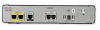
Mounting the VG202 or VG204 Voice Gateway on a Wall, Step 1 - power supply
 |
View all Cisco VG202 manuals
Add to My Manuals
Save this manual to your list of manuals |
Page 34 highlights
Wall-Mounting the Chassis Chapter 3 Installing Cisco VG202 and Cisco VG204 Voice Gateways • The power supply must rest on a horizontal surface such as the floor or a table. If the power supply is not supported, it could place strain on the power supply cable and cause it to disconnect from the connector on the voice gateway back panel. To wall-mount a Cisco VG202 or VG204 voice gateway, follow these steps: Step 1 Step 2 Step 3 Secure two screws 5 7/16 inches (13.81 centimeters) apart into a wall and 5/32 inch (0.40 centimeter) from the wall. Hang the voice gateway on the screws as shown in Figure 3-3. Place the power supply on a horizontal surface. Figure 3-3 Mounting the VG202 or VG204 Voice Gateway on a Wall 1 2 3 7 4 Cisco VG202 and Cisco VG204 Voice Gateways Hardware Installation Guide 3-6 5 6 OL-15959-01 231985
-
 1
1 -
2
-
3
-
4
-
5
-
6
-
7
-
8
-
9
-
10
-
11
-
12
-
13
-
14
-
15
-
16
-
17
-
18
-
19
-
20
-
21
-
22
-
23
-
24
-
25
-
26
-
27
-
28
-
 29
29 -
 30
30 -
 31
31 -
 32
32 -
 33
33 -
 34
34 -
 35
35 -
 36
36 -
 37
37 -
 38
38 -
 39
39 -
40
-
41
-
42
-
43
-
44
-
45
-
46
-
47
-
48
-
49
-
50
 |
 |
