Cisco VG202 Hardware Installation Guide - Page 20
LEDs, Cisco VG204 Voice Gateway LEDs, Table 1-1, Cisco VG202 and Cisco VG204 LEDs
 |
View all Cisco VG202 manuals
Add to My Manuals
Save this manual to your list of manuals |
Page 20 highlights
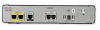
Physical Description Chapter 1 Overview of the Cisco VG202 and Cisco VG204 Voice Gateways LEDs Figure 1-5 shows the LEDs on the Cisco VG204 voice gateway. All LEDs are on the front of the chassis. Note LEDs on the Cisco VG202 and Cisco VG204 are the same; however, the Cisco VG202 has LEDs for only two FXS ports. Table 1-1 describes the status of each LED on the Cisco VG202 and Cisco VG204. Figure 1-5 Cisco VG204 Voice Gateway LEDs 1 2 3 FXS FE OK 0/0 0/1 0/2 0/3 0/0 0/1 272226 OK 0/0 0/1 FXS 0/2 0/3 0/0 FE 0/1 VG204 1 OK LED 3 Fast Ethernet 0/0 and 0/1 LEDs 2 FXS0, FXS1, FXS2, FXS3 LEDs Table 1-1 Cisco VG202 and Cisco VG204 LEDs No LED/Color 1 PWR OK-green 2 FXS ports 0 through 3-green 3 FE ports 0/1-green Description Off-no power Steady on-normal operation Slow blink-bootup phase or in ROMMON monitor mode Off-On hook Steady On-Off hook Off-No link Steady on-link Blinking-TXD/RXD data Cisco VG202 and Cisco VG204 Voice Gateways Hardware Installation Guide 1-4 OL-15959-01
-
 1
1 -
2
-
3
-
4
-
5
-
6
-
7
-
8
-
9
-
10
-
11
-
12
-
13
-
14
-
 15
15 -
 16
16 -
 17
17 -
 18
18 -
 19
19 -
 20
20 -
 21
21 -
 22
22 -
 23
23 -
 24
24 -
 25
25 -
26
-
27
-
28
-
29
-
30
-
31
-
32
-
33
-
34
-
35
-
36
-
37
-
38
-
39
-
40
-
41
-
42
-
43
-
44
-
45
-
46
-
47
-
48
-
49
-
50
 |
 |
