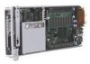
Compaq BL10e HP ProLiant BL e-Class System Setup and Installation Guide - Page 7
List of s, Removing a DIMM
 |
UPC - 613326445501
View all Compaq BL10e manuals
Add to My Manuals
Save this manual to your list of manuals |
Page 7 highlights
Contents List of Figures 1-1 ProLiant BL e-Class server blade enclosure with ProLiant BL e-Class server blades (20)...1-3 1-2 ProLiant BL10e server blade 1-7 1-3 ProLiant BL10e G2 server blade 1-7 2-1 ProLiant BL e-Class standard rack mounting hardware 2-8 2-2 The available interconnect trays 2-9 3-1 Removing a hot-plug power supply 3-2 3-2 Pulling the interconnect tray ejector levers 3-3 3-3 Inserting the interconnect tray and engaging the interconnect tray levers 3-4 3-4 Installing a hot-plug power supply 3-5 3-5 Measuring with the ProLiant BL e-Class rack template 3-6 3-6 Marking the rack for ProLiant BL e-Class system installation 3-7 3-7 Unlocking and adjusting a rack rail 3-8 3-8 Inserting the rear of the rack rail 3-9 3-9 Inserting the front of the rack rail and engaging the locking gear 3-10 3-10 Installing the enclosure into the rack 3-12 3-11 Removing a thumbscrew and hexagonal washer 3-13 3-12 Replacing a thumbscrew, spring, and hexagonal washer 3-14 3-13 Interconnect switch connectors 3-15 3-14 RJ-21 patch panel connectors 3-16 3-15 RJ-45 patch panel connectors 3-17 3-16 Cabling the system with the interconnect switch 3-20 3-17 Cabling the system with the RJ-21 patch panel 3-21 3-18 Cabling the system with the RJ-45 patch panel 3-21 3-19 Powering down the server blade 3-24 3-20 Removing a single-bay server blade blank 3-26 3-21 Removing a five-bay server blade blank 3-27 3-22 Installing a server blade 3-28 3-23 Removing a server blade 3-29 3-24 ProLiant BL10e server blade DIMM socket keys 3-31 3-25 ProLiant BL10e G2 server blade DIMM socket keys 3-32 3-26 Removing a DIMM 3-33 3-27 Installing a DIMM 3-34 3-28 Attaching the diagnostic adapter 3-35 3-29 Connectors on the diagnostic adapter 3-36 HP ProLiant BL e-Class System Setup and Installation Guide vii
-
 1
1 -
 2
2 -
 3
3 -
 4
4 -
 5
5 -
 6
6 -
 7
7 -
 8
8 -
 9
9 -
 10
10 -
 11
11 -
 12
12 -
13
-
14
-
15
-
16
-
17
-
18
-
19
-
20
-
21
-
22
-
23
-
24
-
25
-
26
-
27
-
28
-
29
-
30
-
31
-
32
-
33
-
34
-
35
-
36
-
37
-
38
-
39
-
40
-
41
-
42
-
43
-
44
-
45
-
46
-
47
-
48
-
49
-
50
-
51
-
52
-
53
-
54
-
55
-
56
-
57
-
58
-
59
-
60
-
61
-
62
-
63
-
64
-
65
-
66
-
67
-
68
-
69
-
70
-
71
-
72
-
73
-
74
-
75
-
76
-
77
-
78
-
79
-
80
-
81
-
82
-
83
-
84
-
85
-
86
-
87
-
88
-
89
-
90
-
91
-
92
-
93
-
94
-
95
-
96
-
97
-
98
-
99
-
100
-
101
-
102
-
103
-
104
-
105
-
106
-
107
-
108
-
109
-
110
-
111
-
112
-
113
-
114
-
115
-
116
-
117
-
118
-
119
-
120
-
121
-
122
-
123
-
124
-
125
-
126
-
127
-
128
-
129
-
130
-
131
-
132
-
133
-
134
-
135
-
136
-
137
-
138
-
139
-
140
-
141
-
142
-
143
-
144
-
145
-
146
-
147
-
148
-
149
-
150
-
151
-
152
-
153
-
154
-
155
-
156
 |
 |
