Compaq Presario R4000 HP Pavilion zv6000 Notebook PC and Compaq Presario R4000 - Page 159
of the expansion port 2 connector that secure the system
 |
View all Compaq Presario R4000 manuals
Add to My Manuals
Save this manual to your list of manuals |
Page 159 highlights
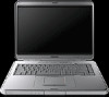
Removal and Replacement Procedures 3. Turn the notebook upside down with the front toward you. 4. Position the top cover with the front toward you. 5. Remove the four PM2.0×7.0 screws 1 that secure the system board to the top cover. 6. Remove the two SM1.5×8.0 shoulder screws 2 on each side of the expansion port 2 connector that secure the system board to the top cover. ✎ Step 7 applies only to Compaq Presario R4000 models. 7. Disconnect the LED cable 3 from the system board. Removing the System Board Screws Maintenance and Service Guide 5-69
-
 1
1 -
2
-
3
-
4
-
5
-
6
-
7
-
8
-
9
-
10
-
11
-
12
-
13
-
14
-
15
-
16
-
17
-
18
-
19
-
20
-
21
-
22
-
23
-
24
-
25
-
26
-
27
-
28
-
29
-
30
-
31
-
32
-
33
-
34
-
35
-
36
-
37
-
38
-
39
-
40
-
41
-
42
-
43
-
44
-
45
-
46
-
47
-
48
-
49
-
50
-
51
-
52
-
53
-
54
-
55
-
56
-
57
-
58
-
59
-
60
-
61
-
62
-
63
-
64
-
65
-
66
-
67
-
68
-
69
-
70
-
71
-
72
-
73
-
74
-
75
-
76
-
77
-
78
-
79
-
80
-
81
-
82
-
83
-
84
-
85
-
86
-
87
-
88
-
89
-
90
-
91
-
92
-
93
-
94
-
95
-
96
-
97
-
98
-
99
-
100
-
101
-
102
-
103
-
104
-
105
-
106
-
107
-
108
-
109
-
110
-
111
-
112
-
113
-
114
-
115
-
116
-
117
-
118
-
119
-
120
-
121
-
122
-
123
-
124
-
125
-
126
-
127
-
128
-
129
-
130
-
131
-
132
-
133
-
134
-
135
-
136
-
137
-
138
-
139
-
140
-
141
-
142
-
143
-
144
-
145
-
146
-
147
-
148
-
149
-
150
-
151
-
152
-
153
-
 154
154 -
 155
155 -
 156
156 -
 157
157 -
 158
158 -
 159
159 -
 160
160 -
 161
161 -
 162
162 -
 163
163 -
 164
164 -
165
-
166
-
167
-
168
-
169
-
170
-
171
-
172
-
173
-
174
-
175
-
176
-
177
-
178
-
179
-
180
-
181
-
182
-
183
-
184
-
185
-
186
-
187
-
188
-
189
-
190
-
191
-
192
-
193
-
194
-
195
-
196
-
197
-
198
-
199
-
200
-
201
-
202
-
203
-
204
-
205
-
206
-
207
-
208
-
209
-
210
-
211
-
212
-
213
-
214
-
215
-
216
-
217
-
218
-
219
-
220
-
221
 |
 |

Removal and Replacement Procedures
Maintenance and Service Guide
5–69
3. Turn the notebook upside down with the front toward you.
4. Position the top cover with the front toward you.
5.
Remove the four PM2.0×7.0 screws
1
that secure the system
board to the top cover.
6. Remove the two SM1.5×8.0 shoulder screws
2
on each side
of the expansion port 2 connector that secure the system
board to the top cover.
✎
Step 7 applies only to Compaq Presario R4000 models.
7. Disconnect the LED cable
3
from the system board.
Removing the System Board Screws