Craftsman 21217 Operation Manual - Page 20
Bevelcutfig.v
 |
View all Craftsman 21217 manuals
Add to My Manuals
Save this manual to your list of manuals |
Page 20 highlights
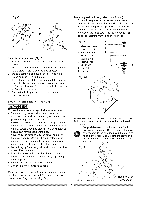
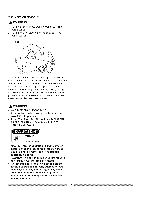
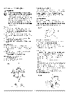
BEVELCUT(FIG.V) WARNING The sliding fence must to be extended when marking any bevel cut. Failure to extend the sliding fence will not allow enough space for the blade to pass through which could result in serious injury. At extreme miter or bevel angles the saw blade may also contact the fence. 1. When a bevel cut is required, loosen the bevel lock handle (1). 2. Tilt the cutting head to the desired angle as shown on the bevel scale (2). The blade can be positioned at any angle, from a 90 ° straight cut (0° on the scale) to a 45 ° left bevel. 3. Tighten the bevel lock handle (1) to lock the cutting head in position. Fig. V COMPOUND CUT (FIG. X) A compound cut is the combination of a miter and a bevel cut simultaneously. 1. Loosen the bevel lock handle (1) and position the cutting head at the desired bevel position, Lock the bevel lock handle. 2. Loosen the miter table lock handle (2). Press down the positive stop locking lever (3) and position the table at the desired angle. Release the positive stop locking lever and lock the miter handle, Fig. X NOTE: The saw comes with a 33.9 ° bevel detent pin for setting up crown molding cuts when the an_ the walls equals 90 °. 33.9 ° BEVEL DETENT PiN FOR CROWN MOLDING (FIG. W) 1. Push the bevel detent stop pin (2) in toward the front of the machine. 2. Loosen the bevel lock handle (1). 3. Rotate the cutting head until the bevel detent pin stops the bevel angle at 33.9 ° on the bevel scale. 4. Tighten the bevel lock handle before you make your cut. Fig. W 2 3 2 CUTTING BOWED MATERIAL (FIG. Y) A bowed workpiece must be positioned against the fence and secured with a clamping device as shown before cutting. Do not position workpiece incorrectly or try to cut the workpiece without the support of the fence, This will cause the blade to bind and could result in personal injury, Fig. Y 2O
-
 1
1 -
2
-
3
-
4
-
5
-
6
-
7
-
8
-
9
-
10
-
11
-
12
-
13
-
14
-
 15
15 -
 16
16 -
 17
17 -
 18
18 -
 19
19 -
 20
20 -
 21
21 -
 22
22 -
 23
23 -
 24
24 -
 25
25 -
26
-
27
-
28
 |
 |
