Craftsman 21217 Operation Manual - Page 22
chart, compound, cut crown, inside, corner=Left, corner-Right
 |
View all Craftsman 21217 manuals
Add to My Manuals
Save this manual to your list of manuals |
Page 22 highlights
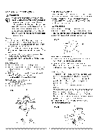
CUTTINGBASEMOLDING(FIG.CC) Basemoldingasndmanyothermoldingcsanbecuton a compoundmitersaw.Thesetupofthesawdepends onmoldingcharacteristicasndapplicationa,s shown. Performpracticecutsonscrapmateriatlo achievebest results: 1. Alwaysmakesuremoldingsrestfirmlyagainsftence andtable.Usehold-downorC-clampsw, henever possiblea, ndplacetapeontheareabeingclamped to avoidmarks. 2. Reducesplinteringbytapingthecutareapriorto makingcut. Markcut linedirectlyon thetape. 3. Splinterintgypicallyhappendsuetowrongblade applicatioanndthinnessofthe material. Fig.CC F e n c Fig. DD FI el nl cl el 1 Miter saw table Bevel/Miter Settings Fig. EE Settings for standard crown molding lying flat on compound miter saw table Inside Corner \ OR MiterSawTable Miter Saw Table I miterat45°,beveal t0° miter at 0°, bevel at 45o NOTE: Always perform a dry run cut so you can determine if the operation being attempted is possible before power is applied to the saw. CUTTING CROWN MOLDING (FIG. DD, EE) NOTE: The chart below references a compound cut for crown molding ONLY WHEN THE ANGLE BETWEEN THE WALLS EQUALS EXACTLY 90 °. Your compound miter saw is suited for the difficult task of cutting crown molding. To fit properly, crown molding must be compound-mitered with extreme accuracy. The two surfaces on a piece of crown molding that fit flat against the ceiling and wall are at angles that, when added together equal exactly 90 ° . Most crown molding has a top rear angle (the section that fits flat against the ceiling) of 52°and a bottom rear angle (the section that fits flat against the wall) of 38 ° . In order to accurately cut crown molding for a 90 ° inside or outside corner, lay the molding with its broad back surface flat on the saw table. IL \ Outside Corner Compound Cut Crown Moldings NOTE: The chart below references a compound cut for crown molding ONLY WHEN THE ANGLE BETWEEN THE WALLS EQUALS EXACTLY 90 °. SBETTEINVG ElSLEMTTIINTGE_ IR TYPE OF CUT Inside corner=Left side IL 33.9 ° _R_33.9 ° OL _339° O_33.9 ° I3R1ig,6hto 1_3L1e.f6t ° _Le6ft°131 IR31.g6h°t 2, Miter table set at RIGHT 31.6 _. 13. ..1, PLEosFiTtionsidteopisofifnimshoelddingpiagainst f ..... Inside corner-Right side 1, Position bottom of molding against fence. 12, Miter table set at LEFT 31,6h [3. LEFT side is finished piece. Outside corner=Left side 1, Position bottom of molding against fence. 2, Miter table set at LEFT 31.6. _3. RIGHT side is finished piece. Outside corner-Right side 1. Position top of molding against fence. 12. Miter table set at RIGHT 31.6h _3. RIGHT side is finished piece. When setting the bevel and miter angles for compound miters, remember that the settings are interdependent; changing one changes the other, as well. 22
-
 1
1 -
2
-
3
-
4
-
5
-
6
-
7
-
8
-
9
-
10
-
11
-
12
-
13
-
14
-
15
-
16
-
 17
17 -
 18
18 -
 19
19 -
 20
20 -
 21
21 -
 22
22 -
 23
23 -
 24
24 -
 25
25 -
 26
26 -
 27
27 -
28
 |
 |
