Craftsman 21833 Operation Manual - Page 10
I_HP, 3550 RPM, capacitorstart - fence
 |
View all Craftsman 21833 manuals
Add to My Manuals
Save this manual to your list of manuals |
Page 10 highlights
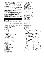
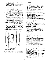
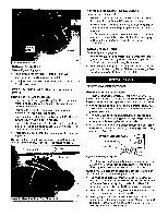
Rip Fence Dimensions: Rip fence Rip fence rails (front and rear Blade capacity maximum Blade arbor Dado blade capacity maximum 31¼" 56_" 10" %" ,¾g' Saw Constructions: Cabinet Table Totallyenclosedsteel panel Cast iron Ripfence Aluminum tube Drive system V-belt Exhaust port 4" Male Miter gauge Cast ironwithT-slotroller guide Blade guard Acrylic with anti-kickback pawls Switch Lockingpaddle switch with overload Arbor R.RM 3450 RPM approx. Motor I_HP, 3550 RPM, capacitorstart, capacitor run, 120/240V, 15/7.5A, single-phase, ball bearing Gross weight with motor 308 lbs WARNING: Disconnect power before attempting any of the following procedures. Be certain switch is in OFF position and safety disconnect (or breaker) is in OFF or open position. Saw blade must not be moving. Saw blade will rotate freely after motor is turned off. Allow blade to come to a complete stop before attempting any of the following procedures. WARNING: The operation of any power tool can result in foreign objects being thrown into the eyes, which can result in severe eye damage. Aiways wear safety goggles complying with United States ANSI Z87.1 before commencing power tool operation. STARTING AND STOPPING THE SAW Refer to Figure 11, page 22. WARNING: Never operatesaw withoutblade guardsin place.Be sure blade is not in contactwith workpiecewhen motor is started.Start motorand allow saw to cometo full speed. WARNING: Make sure the electricalcharacteristicsof motor nameplateand powersource are the same. • The ON/OFF switch is locatedunder the front railof the table saw at the left side. • To turnsaw on, stand to either side of the bladewnever in line with it. Pull up switch (Key No. 2). Always allowsaw blade to come up to fult speed beforecutting. • Do not turnmotor switch ON and OFF rapidly.This action overheatsthe motorand may cause saw blade to loosen. ° Never leave saw while the poweris on. • To turnthe table saw off, pressthe largered OFF paddle (KeyNo. I). Never leave saw until cuttingtoolhas come to a completestop. WARNING: Foryour own safety, lowerblade or cuttingtool below table surface. If blade istilted, return it to verticalposition.Turn offsafety disconnector circuitbreakerwhen saw is not in use. BLADE HEIGHT ADJUSTMENT Refer to Figure 13, page 26. * Blade height is controlled by handwheel (Key No. 30) on the front of the saw. • To adjust height, loosen locking hand knob (Key No. 27). Rotate knob counterclockwise approximately three turns. Turn handwheel to desired blade height. CAUTION: For safety, blade should be raised only %" above the surface of the material to be cut. However, if hollow ground blades are used, raise blade to its maximum height to allow for greater blade clearance. • Lock blade height into position. Lock handwhee] (Key No. 30) by tightening locking knob (Key No. 27) clockwise. Tighten only until snug. IMPORTANT: Do not over tighten. Only a small amount of pressure is necessary to lock handwheel securely. BLADE TILT ADJUSTMENT Refer to Figure 13, page 26. ° The saw blade can be set at any angle between 90° and 45°. Blade tilt iscontrolledby the handwheel (Key No.30) on the rightside of the saw.The indicator (Key No. 86) on front of saw showsthe tilt angle of the blade. • To adjusttilt, loosen lockinghandknob(Key No. 27). Rotateknob counterclockwiseat leastthree turns.Turn handwhee]to desiredblade angle. Lockblade angle into position. ° Lockhandwhee](Key No. 30) by tighteninglockinghand knob (Key No. 27) clockwiseT. ightenonly untilsnug. ° The saw is equipped with positivestops at 90° and 45 °. These positivestopsallow operatorto positionsaw blade at 90° and 45° quickly and accurately. 90 ° STOP ADJUSTMENT Refer to Figures 11 and 13, pages 22 and 26. ° Raise saw blade above table as far as possible.Set blade at 90° to table by turningthe tiltinghandwheel.Place a square on table and checkto see if blade is perpendicular to the table.When checkingput square flush against saw blade.Do not put square on teeth of saw blade. • If the bladewill not tilt to 90 °, turn (counterclockwiset)he set screw(Fig. 11, Key No. 44) at the left front of the table insert untilthe blade can be positionedto 90°. ° Once the blade has been tiltedto 90° (confirm this using yoursquare), tightenthe bevel handwheellock knob, locatedon the side of the cabinet.This will keep the blade from tiltingfurther. ° Turn the set screw (clockwise)until it comes in contact withthe positivestop. • Check tilt indicatorpointer,if necessary, adjust pointerso it points to 0° mark on scale. To adjustpointer,remove handwheeland loosenscrew (Fig. 13, Key No. 84). Be sure to tightenscrew securely after adjustmentis completed. 45 ° STOP ADJUSTMENT Refer to Figure I1, page 22. • Tiltthe saw bladeto 45 °. Usinga combinationsquare, checkto see if blade is 45° to the table. ° If the bladewill not tilt to 45 °, turn (counterclockwiset)he set screw (Key No. 44) locatedat the rightof the table insert, untilthe blade can be positioned to 45°. 10
-
 1
1 -
2
-
3
-
4
-
 5
5 -
 6
6 -
 7
7 -
 8
8 -
 9
9 -
 10
10 -
 11
11 -
 12
12 -
 13
13 -
 14
14 -
 15
15 -
16
-
17
-
18
-
19
-
20
-
21
-
22
-
23
-
24
-
25
-
26
-
27
-
28
-
29
 |
 |
