Craftsman 21833 Operation Manual - Page 11
Table Insert Adjustment - dado insert
 |
View all Craftsman 21833 manuals
Add to My Manuals
Save this manual to your list of manuals |
Page 11 highlights
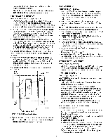
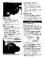
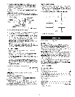
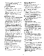
• With the blade at 45 °, tighten the bevel handwheel lock knob to keep the blade from further tilting. • Turn the set screw clockwise until it comes in contact with the positive stop. TABLE INSERT ADJUSTMENT Refer to Figure i1, page 22. ° The table insert (Key No. 41) must always be level with the saw table. • Place a straight edge across the front and rear of the table insert. Check that the insert is perfectly level with the saw table. ° To level the table insert, turn one or more adjusting set screws (Key No. 42) as needed and recheck. • The table insert is equipped with a finger hold for easy removal. MITER GAUGE ADJUSTMENT • Miter gauge supplied with saw is equipped with individually adjustable index stops at 0° and 45 °, right and left, and can be manually adjusted up to 60 ° right and left. Adjustment to index stops can be made by loosening locking nut and tightening or loosening three adjusting screws. Be sure to tighten locking nut after adjustment is made. • Face of miter gauge has two holes for purpose of attaching auxiliary facing. • Miter gauge is accurately constructed for precision work. Miter gauge is guided through T-slot with a roller guide mounted at front of guide bar. Roger guide adds to miter gauge's stability and prevents the guide bar from leaving T-slot. To operate miter gauge, simply loosen lock handle and move miter gauge to desired angle. The miter gauge will stop at 0° and 45 °, both right and left. To position miter gauge past these points, simply pull out gauge stop. Position miter gauge at desired angle and tighten lock handle. • Be positive the edge of workpiece next to face of miter gauge is straight and tight against miter gauge so that the workpiece does not rock or rotate. Always use both hands when operating the miter gauge. ° The miter gauge is used for cross-cutting, compound miter cutting, miter cutting, rabbeting, bevel cutting and dadoing. RIP FENCE ADJUSTMENT Refer to Figure 9, page 18. The saw's rip fence is precisionmanufactured, incorporating fine adjustmentsfor accurate cuts.The saw is built to allow the operatorto accuratelyadjustthe rip fence withoutproblems in a matter of seconds. LEVELING THE FENCE TO THE TABLE Refer to Figure 9, page 18. • Liftthe lockhandle (Key No. 2) to unlockthe fence. • Observe the space between the fence bottom and the table.The spaceshould be equa] along the entire length of the fence. • If the space is not equal, the railsneed to be adjusted. See Rail Assembly, page 7. SETTING CLAMPING PRESSURE Refer to Figure 9, page 18. Rip fence has been adjusted at the factory to locksecurely when the lock handle is pusheddown. To adjust: * Unlockfence and remove it from the rails. ° Adjust the hex nut (Key No.31) untilthe fence is held securelywhen the lock handle ispushed down, SETTING FENCE PERPENDICULAR Refer to Figure 9, page 18. = Positionfence anywhereon table and lockit down. • Place a squareon the table nextto the fence and checkto see thatthe fence is at 90° to the table. ° If an adjustmentis necessary,unlockthe fence and turn eitherof the two front adjustingscrews (Key No.13). NOTE: This is for micro-adjustment only.If fence cannot be adjustedsquare, recheck rail adjustment. ° Lockthe fencein positionand recheck. Continue this procedureuntilthe fence is squareto the table. CURSOR ADJUSTMENT Refer to Figure 9, page 18. ° Raise the saw blade above the table. ° Positionthe fence several inchesto the rightof the saw blade. • Lockthe fence down and measurethe exact distance betweenthe saw blade and the insideof the fence. ° Loosenthe two screws (Key No. i6) on the lens and slide it left or rightuntilthe cursor(red line)equalsthe measurement obtainedin the previousstep. ° Retightenthe screws and make a test cut. Measure the cut pieceto verifythat the cursoris set correctly. NOTE: This adjustmentshouldbe checkedwhenevera new blade is installed. RIP FENCE OPERATION Refer to Figure 9, page 18. • Unlock the fence by lifting the locking lever (Key No. 2). Using the scale for placement, position the rip fence. Lock the rip fence into position by placing the locking lever in the down position. • The rip fence is used for the following operations: ripping, bevel ripping, ploughing, resawing, rabbeting and dadoing. INSTALLING AND REMOVING THE RIVING KNIFE Refer to Figure 13, page 26. Install ° Line up the rivingknife (Key No. 51) in the properdirection to the mountingbracket (Key No. 47). ° Push the rivingknifeall the way down into the mounting bracket.Make sure the lock pin (Key No.48) is lockedin the hole of the rivingknife. (The lock hole is on the button side of the rivingknife). • If it is not lockedproperly, hold the fastening knob (Key No. 54) and pull the lockpin offand make sure the lockpinis properlylocatedat the hole of riving knife.While raisingor loweringthe knife, pin willsnap in the holeof the knifewhen locatedat one of the three positions. ° Tighten the fastening knob. 11
-
 1
1 -
2
-
3
-
4
-
5
-
 6
6 -
 7
7 -
 8
8 -
 9
9 -
 10
10 -
 11
11 -
 12
12 -
 13
13 -
 14
14 -
 15
15 -
 16
16 -
17
-
18
-
19
-
20
-
21
-
22
-
23
-
24
-
25
-
26
-
27
-
28
-
29
 |
 |
