Craftsman 21833 Operation Manual - Page 8
adjusted. See Operation, Rip Fence - rating
 |
View all Craftsman 21833 manuals
Add to My Manuals
Save this manual to your list of manuals |
Page 8 highlights
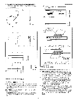
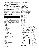
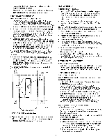
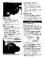
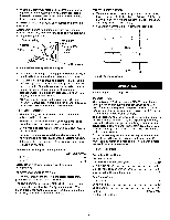
Locking Pin Figure 4 - Riving Knife INSTALL TABLE INSERT Refer to Figure 11, page 22. ° Place table insert (Key No. 41) into throat of table. • Insert is held in position by magnet in table. • To adjust insert level with table, adjust leveling screws (Key No. 42) up or down. ATTACH BLADE GUARD AND ANTI-KICKBACK PAWLS Refer to Figures 5 and 14, page 28. • Placethe slot of blade guard body (Key No. 11) over the riving knife.Throughbolt of guard is placed in the notch indicatedin Figure5. • Positionguard completelydownon rivingknifeand press latch (Key No. 16) to lock in position. ° Bladeguard body should be parallel to the table.Use set screws(Key No. 8) to adjustif needed. • Place anti-kickbackpawl set onto rivingknifeat notches indicated.The springpin is placedin the front notchand bolt is placed in the rear notch. ° Press pawl set completelydown and press latchto secure in position. NOTE: The teeth of anti-kickback pawls should touchtable surface. Use set screws (Key No. 17) to adjust if needed. RIP FENCE ASSEMBLY INSTALLATION Refer to Figure 9, page 18. ° Positionrip fence assembly at end of saw. Be certainlock- ing lever (Key No.2) is in UP unlockedposition. ° Place rip fence assembly onto rails,positioningclamp (No. 26) over rear rail and then placingripfence ontofront guide rail. ° Rip fence should now ride freely on rip fence rails. Once rip fence is completely installed, it should be thoroughly adjusted. (See Operation, page 11, Rip Fence Adjustment.) INSTALL MITER GAUGE Refer to Figure 14, page 28. ° The mitergauge comespreassembled.Unpackthe miter gauge and clean thoroughlyB. e certain mitergauge T-slotsin table are also thoroughlycleaned. ° The mitergauge is guidedthroughthe T-slotwith a roller guide at the frontof guidebar. To insertmiter gauge, first insert rollerguideintoT-slotat front of table. ELECTRICAL CONNECTIONS GROUNDING INSTRUCTIONS WARNING: improperconnectionof equipmentgrounding conductorcan resultin the riskofelectricasl hock.Equipmenst hould be grounded whilein usetoprotectoperatorfrom electricasl hock. • Check with a qualifiedelectrician if groundinginstructions are not understoodor if in doubtas to whetherthe tool is properlygrounded. • Thistool isequippedwith an approved3-conductorcord rated at 300V and a 3-pronggroundingtypeplug(see Figure 6) for yourprotectionagainst shock hazards. • Grounding plug should be pluggeddirectlyintoa properly installedand grounded3-prong grounding-typereceptacle, as shown (Figure6). Properly Grounded Outlet Grounding Prong iBlade Guard Pawl Set 3-Prong Plug ___ Figure 6 - 3-Prong Receptacle ° Do not remove or alter grounding prong in any manner. In the event of a malfunction or breakdown, grounding provides a path of least resistance for electrical shock. WARNING: Do not permit fingers to touch the terminals of plug when installing or removing from outlet. • Plug must be plugged into matching outlet that is properly installed and grounded in accordance with all local codes and ordinances. Do not modify plug provided. If it will not fit in outlet, have proper outlet installed by a qualified electrician. ° Inspect tool cords periodically and if damaged, have them repaired by an authorized service facility. • Green (or green and yellow) conductor in cord is the grounding wire. If repair or replacement of the electric cord or plug is necessary, do not connect the green (or green and yellow) wire to a live terminal. 8
-
 1
1 -
2
-
 3
3 -
 4
4 -
 5
5 -
 6
6 -
 7
7 -
 8
8 -
 9
9 -
 10
10 -
 11
11 -
 12
12 -
 13
13 -
14
-
15
-
16
-
17
-
18
-
19
-
20
-
21
-
22
-
23
-
24
-
25
-
26
-
27
-
28
-
29
 |
 |
