Cub Cadet LS 25 CC H Operation Manual - Page 5
Assembly & Set-Up
 |
View all Cub Cadet LS 25 CC H manuals
Add to My Manuals
Save this manual to your list of manuals |
Page 5 highlights
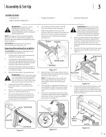
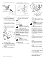
Assembly & Set-Up 3 Contents of Carton • Log Splitter (1) • Engine Operator's Manual (1) • Tongue Assembly (1) • Operator's Manual (1) WARNING! Use extreme caution 8. unpacking this machine. Some components are very heavy and will 9. require additional people or mechanical handling equipment. NOTE: All references in this manual to the left or right side and front or back of the log splitter are from the operating position only. Exceptions, if any, will be specified. IMPORTANT: A minimum of two people are recommended to assemble this unit. Unpacking & Assembling the Log Splitter TOOLS NEEDED: Safety glasses, leather gloves, wire cutters, pry bar and/or claw hammer. 1. Use a pry bar or claw hammer to loosen and remove the top of the crate. 2. Use a pry bar or claw hammer to remove the sides of the crate, beginning with the short sides (or left and right side of the log splitter). Set the sides of the crate aside to avoid injury. 3. A cable tie attaches the tongue assembly to the inside, front of the crate. Cut the cable tie to remove the tongue. 4. Remove the large plastic cover and discard. 10. WARNING! Do NOT remove any wood or cut any straps securing the log splitter or its components to the log splitter or the crate at this time. Only remove straps and/or wood when instructed to do so. 5. Inspect the bottom of the crate for any protruding staples or wood splinters and 11. remove. 6. Remove any loose parts included with the log splitter (i.e. Operator's Manual, etc.). 12. 7. Remove the spring clip and clevis pin from the jack stand on the tongue and then pivot the jack stand towards the ground into the operating position. See Figure 3-1. Secure the jack stand in position with the clevis pin and spring clip. See Figure 3-1. With the log splitter still secured to the bottom of the crate, remove two hex bolts and hex nuts from the tank bracket and remove the piece of wood inside the tank brackets. See Figure 3-2. 13. Tongue Hex Nuts 14. WARNING! Take extra care when raising and lowering the beam as it is heavy. Having a second person assist with raising or lowering the beam is recommended. Be sure to keep hands away from any possible pinch points. Remove the wood between the wedge and the end plate by cutting the cable tie that secures it. Cut the strap near the hose on the front of the cylinder that secures it to the beam weld bracket. Be careful not to damage the hose. Disconnect the dislodger from the beam weld bracket by removing the six hex screws. See Figure 3-4. Hex Screws Tank Brackets Hex Bolts Figure 3-2 Align the holes in the tongue with the holes in the tank bracket and secure with the hardware just removed. See Figure 3-2. NOTE: The high pressure hose, which runs from the gear pump to the bottom of the control valve, must be above the tongue assembly. The log splitter is shipped with the beam in a vertical position. Remove any bolts or straps securing the end plate to the bottom of the crate. Pull out the vertical beam lock, rotate it back, and pivot the beam to the horizontal position until it locks. Be sure to avoid any possible pinch points. See Figure 3-3 Hex Screws Dislodger Figure 3-4 15. Disconnect the log tray from the beam on the control valve side by removing the two hex washer screws that secure it to the beam weld brackets and the two hex washer screws in the beam. See Figure 3-5. Spring Clip Clevis Pin Jack Stand Figure 3-1 Vertical Beam Lock Figure 3-3 Hex Washer Screw Beam Log Tray Figure 3-5 5
-
 1
1 -
 2
2 -
 3
3 -
 4
4 -
 5
5 -
 6
6 -
 7
7 -
 8
8 -
 9
9 -
 10
10 -
 11
11 -
12
-
13
-
14
-
15
-
16
-
17
-
18
-
19
-
20
-
21
-
22
-
23
-
24
-
25
-
26
-
27
-
28
 |
 |
