Cub Cadet LS 25 CC H Operation Manual - Page 7
Controls & Operation
 |
View all Cub Cadet LS 25 CC H manuals
Add to My Manuals
Save this manual to your list of manuals |
Page 7 highlights
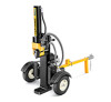
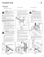
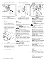
Controls & Operation Cylinder Log Dislodger Tongue Safety Chains Jack Stand Control Handle Wedge Horizontal Beam Lock Beam Log Tray End Plate 4 4. To place the beam in the vertical position proceed as follows: WARNING! Always use the log splitter in the vertical position when splitting heavy logs. a. Pull the horizontal beam lock out to release the beam and pivot the beam to the vertical position. b. To lock the beam in the vertical position, pull vertical beam lock out and rotate it to secure the beam. See Figure 4-3. 2 Vertical Beam Lock 1 Figure 4-1 Controls and Features Operation Engine Controls Starting & Stopping the Engine See the Engine Operator's Manual for the location Refer to the Engine Operator's Manual packed with 5. and function of the engine controls. your log splitter for instructions on starting and Beam Locks stopping the engine. These two locks secure the beam in the horizontal or Operating Positions the vertical position. The vertical beam lock is located 1. Place the log splitter on flat, dry, solid ground. next to the oil filter. The horizontal beam lock is located on the beam support latch bracket. 2. Block the front and back of both wheels. See Figure 4-2. Control Handle The control handle has three positions; Forward, Neutral and Reverse. See the Operation section for instructions. Vertical Wedge The wedge is used to split the wood. Log Dislodger The log dislodger is designed to remove any partially split wood from the wedge. This may occur while splitting large diameter wood or freshly cut wood. Log Tray The log tray is designed to stabilize the log after it is split. Tongue Horizontal The tongue is used to attach to a towing vehicle for transportation. End Plate Figure 4-2 3. Place the beam in either the horizontal or vertical position and lock into place. The end plate holds the log in place while the wedge splits it. Safety Chains The safety chains are hooked to the towing vehicle for transportation NOTE: Take extra care when raising and lowering the beam as it is heavy. Be sure to keep hands away from any possible pinch points. Vertical Beam Lock Figure 4-3 To place the beam in the horizontal position proceed as follows: a. Pull the vertical beam lock out and rotate it down. Pivot the beam to the horizontal position. b. The horizontal beam lock is selflocking. The spring loaded lock will snap into place when the beam is lowered into position. See Figure 4-4. 1 2 Horizontal Beam Lock Figure 4-4 7
-
 1
1 -
 2
2 -
 3
3 -
 4
4 -
 5
5 -
 6
6 -
 7
7 -
 8
8 -
 9
9 -
 10
10 -
 11
11 -
 12
12 -
13
-
14
-
15
-
16
-
17
-
18
-
19
-
20
-
21
-
22
-
23
-
24
-
25
-
26
-
27
-
28
 |
 |
