Dacor ERD30 Installation Instruction - Epicure Range - Page 5
Product Specifications
 |
View all Dacor ERD30 manuals
Add to My Manuals
Save this manual to your list of manuals |
Page 5 highlights
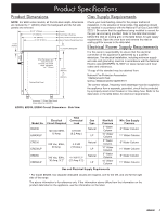
Product Specifications Product Dimensions NOTE: For ERD series models, all front-to-back depth dimensions are reduced by 1" (25mm) when the backguard and the full side panels are removed. 28 1/2" (724mm) 27" (686mm) 26" (660mm) 24 3/8" (619mm) Handle Front Edge of Bullnose Face of Control Panel/Oven Door Rear of Control Panel/Oven Door 1 9/16" (40mm) 6" (152mm) Backguard When Backguard and Side Panels are removed, the overall depth decreases by 1" (25mm) Finished Side Panel 35 3/4" (908mm) to 37" (940mm) Gas Supply Requirements Check your local building codes for the proper method of installation. In the absence of local codes, this appliance should be installed in accordance with the National Fuel Gas Code ANSI Z223.1. Be certain that the appliance being installed is correct for the gas service being provided. Refer to the data label located behind the inlet air cooling grill, or the table below, for gas supply requirements. Open the oven door and remove the inlet air cooling grill for access to the data label. Electrical Power Supply Requirements It is the owner's responsibility to ensure that the electrical connection of this appliance is performed by a qualified electrician. The electrical installation, including minimum supply wire size and grounding, must be in accordance with the National Electric code ANSI/NFPA 70-1993* (or latest revision) and local codes and ordinances. *A copy of this standard may be obtained from: National Fire Protection Association 1 Batterymarch Park Quincy, Massachusetts 02269-9101 The correct voltage, frequency and amperage must be supplied to the appliance from a separate, grounded, circuit that is protected by a properly sized circuit breaker or time delay fuse. Refer to the data label, or the table below, for electrical requirements. Accessory 3" (76mm) Side Panels (Dacor Model No. AESP03) EGR30, ERD30, ERD60 Overall Dimensions - Side View Electrical Model No. Circuit Required EGR30 EGR30LP 120 Vac 60Hz, 15 Amp. Total Connected Load 0.75 kW (6.2 Amp.) Gas Type Natural LP ERD30 ERD30LP 240 Vac, 60Hz, 30 Amp. 4.2 kW (18 Amp.) Natural LP ERD60 ERD60LP 240 Vac, 60Hz, 30 Amp. X 2* 4.1 kW X 2* (21 Amp X 2) Natural LP Manifold Pressure 5" Water Column 10" Water Column 5" Water Column 10" Water Column 5" Water Column 10" Water Column Gas and Electrical Supply Requirements Min. Gas Supply Pressure 6" Water Column 11" Water Column 6" Water Column 11" Water Column 6" Water Column 11" Water Column * For model ERD60, two separate dedicated circuits are required, one for the left, and one for the right side of the range. The above information is for reference only. If the information above differs from the information on the product data label on the appliance, use the information on the label. 3
-
 1
1 -
 2
2 -
 3
3 -
 4
4 -
 5
5 -
 6
6 -
 7
7 -
 8
8 -
 9
9 -
 10
10 -
 11
11 -
12
-
13
-
14
-
15
-
16
 |
 |
