Dacor ERD30 Installation Instruction - Epicure Range - Page 6
Planning the Installation - service manual
 |
View all Dacor ERD30 manuals
Add to My Manuals
Save this manual to your list of manuals |
Page 6 highlights
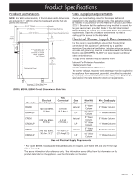
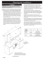
Planning the Installation WARNING • Both the gas supply piping and shut-off valve, and the electrical junction box/receptacle must be located so they do IMPORTANT: Observe all governing codes and ordinances not interfere with the range when it is installed. In addition, during planning and installation. Contact your local building the junction box must be located so the range can be department for further information. removed for service when the conduit supplied with the unit is attached to the junction box. Do not lengthen the conduit or Cabinet and Countertop Preparation wiring provided with the range. • All dimensions shown are based on standard American • The shaded areas shown in the illustrations below show the cabinets 36 inches (914mm) high at the finished countertop recommended location of the gas stub and the electrical by 24 inches (610mm) deep, with a 25 inch (635mm) overall junction box/receptacle in the lower left corner of the adjacent countertop depth. All minimum clearances shown MUST be right cabinet. For replacement purposes, the location of the maintained. existing utilities may be utilized provided that they do not interfere with the sides or rear of the range. If installing the gas valve behind the range, verify that doing so is permitted by local building codes. • Carefully check the location where the range is to be installed. For best performance, the range should be placed away from drafts that may be caused by doors, windows and HVAC outlets. • A manual shut valve must be installed in the gas piping, external to the appliance, for the purpose of turning on or shutting off gas to the appliance. Plan the location of the range and the gas supply to allow access to the valve when the unit is installed. Access to the remote circuit breaker • If cabinet storage space is to be provided directly above the range, the risk of personal injury may be reduced by installing a ventilating hood that projects horizontally a minimum of 5 inches beyond the face of the cabinets. panel/fuse box with the range in place must also be allowed • The range may be installed flush to the rear wall. Dacor for in the installation. Any openings in the wall behind the highly recommends installing a non-combustible material on appliance and in the floor under the appliance must be the rear wall above the range and up to the vent hood. It is sealed. not necessary to install non-combustible materials behind the range below the countertop height. B Model Number "A" "B" ERD30 EGR30 30 1/16" (764mm) 36" (914mm) Recommended 30" (762mm) Minimum ERD60 60 1/8" (1572mm) 66" (1676mm) Recommended 60" (1542mm) Minimum Non-Combustible surface along back wall 30" (762mm) min.* A ** 4 Suggested location of utilities * Vertical to combustible surface ** Cabinet depth is at discretion of customer but cabinet face MUST NOT protrude further than rear of front panel, see product dimesions Cutout Dimensions
-
 1
1 -
 2
2 -
 3
3 -
 4
4 -
 5
5 -
 6
6 -
 7
7 -
 8
8 -
 9
9 -
 10
10 -
 11
11 -
 12
12 -
13
-
14
-
15
-
16
 |
 |
