Dell Dimension 900 Reference Guide - Page 26
System Board, System Board Features
 |
View all Dell Dimension 900 manuals
Add to My Manuals
Save this manual to your list of manuals |
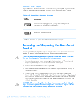
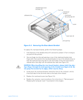
Page 26 highlights
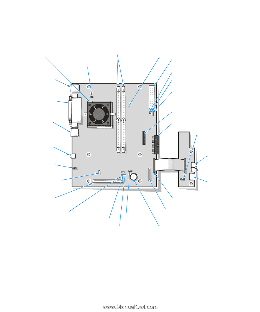
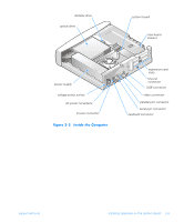
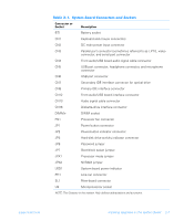
System Board Figure 2-4 shows the system board connectors and sockets, and Table 2-1 describes their functions. microprocessor socket (U9) DIMM sockets (DIMMn) processor fan connector (FN1) keyboard (lower) and mouse (upper) connectors (CN1) parallel port, video, and serial port connectors (CN3) system board power indicator (LED1) DC main power input connector (CN2) power button connector (JP1) power-button indicator connector (JP2) hard-disk drive activity indicator connector (JP3) USB port connector (CN6) line-out connector (PH1) audio signal cable connector (CN13) processor mode jumper (JPX1) riser-board connector (SL1) boot-block select jumper (JP7) NVRAM jumper (JPX2) jumper (not used) password jumper (JP6) secondary IDE interface connector (CN7) primary IDE interface connector (CN8) front audio/USB board audio signal cable connector (CN4) microphone connector (CN5) headphone connector (CN5) USB port connector (CN5) front audio/USB board interface connector (CN12) diskette-drive interface connector (CN16) battery socket (BT1) Figure 2-4. System Board Features 2-6 Dell Dimension 900 System Reference and Troubleshooting Guide
-
 1
1 -
2
-
3
-
4
-
5
-
6
-
7
-
8
-
9
-
10
-
11
-
12
-
13
-
14
-
15
-
16
-
17
-
18
-
19
-
20
-
 21
21 -
 22
22 -
 23
23 -
 24
24 -
 25
25 -
 26
26 -
 27
27 -
 28
28 -
 29
29 -
 30
30 -
 31
31 -
32
-
33
-
34
-
35
-
36
-
37
-
38
-
39
-
40
-
41
-
42
-
43
-
44
-
45
-
46
-
47
-
48
-
49
-
50
-
51
-
52
-
53
-
54
-
55
-
56
-
57
-
58
-
59
-
60
-
61
-
62
-
63
-
64
-
65
-
66
-
67
-
68
-
69
-
70
-
71
-
72
-
73
-
74
-
75
-
76
-
77
-
78
-
79
-
80
-
81
-
82
-
83
-
84
-
85
-
86
-
87
-
88
-
89
-
90
-
91
-
92
-
93
-
94
-
95
-
96
-
97
-
98
-
99
-
100
-
101
-
102
-
103
-
104
-
105
-
106
-
107
-
108
-
109
-
110
-
111
-
112
-
113
-
114
-
115
-
116
-
117
-
118
-
119
-
120
-
121
-
122
 |
 |