Dell Dimension 900 Reference Guide - Page 27
Table 2-1., System Board Connectors and Sockets, Connector or, Socket, Description
 |
View all Dell Dimension 900 manuals
Add to My Manuals
Save this manual to your list of manuals |
Page 27 highlights
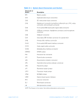
u Table 2-1. System Board Connectors and Sockets Connector or Socket Description BT1 Battery socket CN1 Keyboard and mouse connectors CN2 DC main power input connector CN3 Parallel port connector (sometimes referred to as LPT1), video connector, and serial port connector CN4 Front audio/USB board audio signal cable connector CN5 USB port connector, headphone connector, and microphone connector CN6 USB port connector CN7 Secondary IDE interface connector for optical drive CN8 Primary IDE interface connector CN12 Front audio/USB board interface connector CN13 Audio signal cable connector CN16 Diskette-drive interface connector DIMMn DIMM socket FN1 Processor fan connector JP1 Power button connector JP2 Power-button indicator connector JP3 Hard-disk drive activity indicator connector JP6 Password jumper JP7 Boot-block select jumper JPX1 Processor mode jumper JPX2 NVRAM jumper LED1 System board power indicator PH1 Line-out connector SL1 Riser-board connector U9 Microprocessor socket NOTE: The Glossary in the system Help defines abbreviations and acronyms. support.dell.com Installing Upgrades on the System Board 2-7
-
 1
1 -
2
-
3
-
4
-
5
-
6
-
7
-
8
-
9
-
10
-
11
-
12
-
13
-
14
-
15
-
16
-
17
-
18
-
19
-
20
-
21
-
 22
22 -
 23
23 -
 24
24 -
 25
25 -
 26
26 -
 27
27 -
 28
28 -
 29
29 -
 30
30 -
 31
31 -
 32
32 -
33
-
34
-
35
-
36
-
37
-
38
-
39
-
40
-
41
-
42
-
43
-
44
-
45
-
46
-
47
-
48
-
49
-
50
-
51
-
52
-
53
-
54
-
55
-
56
-
57
-
58
-
59
-
60
-
61
-
62
-
63
-
64
-
65
-
66
-
67
-
68
-
69
-
70
-
71
-
72
-
73
-
74
-
75
-
76
-
77
-
78
-
79
-
80
-
81
-
82
-
83
-
84
-
85
-
86
-
87
-
88
-
89
-
90
-
91
-
92
-
93
-
94
-
95
-
96
-
97
-
98
-
99
-
100
-
101
-
102
-
103
-
104
-
105
-
106
-
107
-
108
-
109
-
110
-
111
-
112
-
113
-
114
-
115
-
116
-
117
-
118
-
119
-
120
-
121
-
122
 |
 |