Dell Inspiron 24 5415 All-in-One Service Manual - Page 64
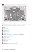
The screws that secure the middle frame and display panel to the display-assembly base are silver in color
 |
View all Dell Inspiron 24 5415 All-in-One manuals
Add to My Manuals
Save this manual to your list of manuals |
Page 64 highlights
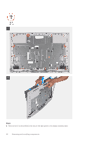
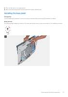
Steps 1. Slide and insert the display panel into the slot on the display-assembly base. 2. Route the display-backlight cable, touchscreen cable, and display cable on the display panel through the slots on the display-assembly base. 3. Place the display-assembly base on a clean and flat surface with the display panel facing down. 4. Replace the 10 screws (M3x5) that secure the display panel to the display-assembly base. 5. Replace the five screws (M3x3) that secure the display panel to the display-assembly base. NOTE: The screws that secure the middle frame and display panel to the display-assembly base are silver in color and etched with "LCD" around the screw holes. Next steps 1. Install the heat sink. 2. Install the M.2 2230 solid-state drive or M.2 2280 solid-state drive, as applicable. 3. Install the wireless card. 4. Install the memory module. 5. Install the system board. 6. Install the system-board shield. 7. Install the hard drive. 8. Install the I/O cover. 9. Install the back cover. 10. Install the stand. 11. Follow the procedure in After working inside your computer. 64 Removing and installing components
-
 1
1 -
2
-
3
-
4
-
5
-
6
-
7
-
8
-
9
-
10
-
11
-
12
-
13
-
14
-
15
-
16
-
17
-
18
-
19
-
20
-
21
-
22
-
23
-
24
-
25
-
26
-
27
-
28
-
29
-
30
-
31
-
32
-
33
-
34
-
35
-
36
-
37
-
38
-
39
-
40
-
41
-
42
-
43
-
44
-
45
-
46
-
47
-
48
-
49
-
50
-
51
-
52
-
53
-
54
-
55
-
56
-
57
-
58
-
 59
59 -
 60
60 -
 61
61 -
 62
62 -
 63
63 -
 64
64 -
 65
65 -
 66
66 -
 67
67 -
 68
68 -
 69
69 -
70
-
71
-
72
-
73
-
74
-
75
-
76
-
77
-
78
-
79
-
80
-
81
-
82
 |
 |
