Dell Inspiron N5110 Service Manual - Page 42
Note the routing of the Mini-Card antenna cables and remove the cables
 |
View all Dell Inspiron N5110 manuals
Add to My Manuals
Save this manual to your list of manuals |
Page 42 highlights
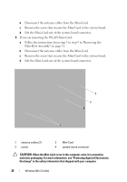
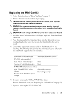
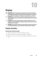
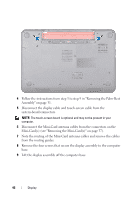
4 Follow the instructions from step 3 to step 9 in "Removing the Palm-Rest Assembly" on page 31. 5 Disconnect the display cable and touch-screen cable from the system-board connectors. NOTE: The touch-screen board is optional and may not be present in your computer. 6 Disconnect the Mini-Card antenna cables from the connectors on the Mini-Card(s) (see "Removing the Mini-Card(s)" on page 37). 7 Note the routing of the Mini-Card antenna cables and remove the cables from the routing guides. 8 Remove the four screws that secure the display assembly to the computer base. 9 Lift the display assembly off the computer base. 42 Display
-
 1
1 -
2
-
3
-
4
-
5
-
6
-
7
-
8
-
9
-
10
-
11
-
12
-
13
-
14
-
15
-
16
-
17
-
18
-
19
-
20
-
21
-
22
-
23
-
24
-
25
-
26
-
27
-
28
-
29
-
30
-
31
-
32
-
33
-
34
-
35
-
36
-
 37
37 -
 38
38 -
 39
39 -
 40
40 -
 41
41 -
 42
42 -
 43
43 -
 44
44 -
 45
45 -
 46
46 -
 47
47 -
48
-
49
-
50
-
51
-
52
-
53
-
54
-
55
-
56
-
57
-
58
-
59
-
60
-
61
-
62
-
63
-
64
-
65
-
66
-
67
-
68
-
69
-
70
-
71
-
72
-
73
-
74
-
75
-
76
-
77
-
78
-
79
-
80
-
81
-
82
-
83
-
84
-
85
-
86
-
87
-
88
-
89
-
90
 |
 |

42
Display
4
Follow the instructions from step 3 to step 9 in "Removing the Palm-Rest
Assembly" on page 31.
5
Disconnect the display cable and touch-screen cable from the
system-board connectors.
NOTE:
The touch-screen board is optional and may not be present in your
computer.
6
Disconnect the Mini-Card antenna cables from the connectors on the
Mini-Card(s) (see "Removing the Mini-Card(s)" on page 37).
7
Note the routing of the Mini-Card antenna cables and remove the cables
from the routing guides.
8
Remove the four screws that secure the display assembly to the computer
base.
9
Lift the display assembly off the computer base.