Dell Inspiron N5110 Service Manual - Page 58
Replacing the Camera Module
 |
View all Dell Inspiron N5110 manuals
Add to My Manuals
Save this manual to your list of manuals |
Page 58 highlights
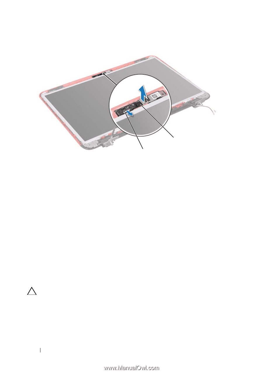
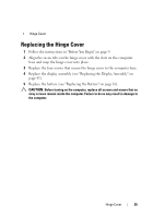
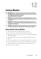
2 1 1 camera module cable connector 2 camera module Replacing the Camera Module 1 Follow the instructions in "Before You Begin" on page 9. 2 Use the alignment posts on the display back cover to place the camera module in position and adhere it in place. 3 Replace the display panel (see "Replacing the Display Panel" on page 47). 4 Replace the display bezel (see "Replacing the Display Bezel" on page 45). 5 Replace the display assembly (see "Replacing the Display Assembly" on page 43). 6 Follow the instructions from step 2 to step 7 in "Replacing the Palm-Rest Assembly" on page 34. 7 Replace the battery (see "Replacing the Battery" on page 16). CAUTION: Before turning on the computer, replace all screws and ensure that no stray screws remain inside the computer. Failure to do so may result in damage to the computer. 58 Camera Module
-
 1
1 -
2
-
3
-
4
-
5
-
6
-
7
-
8
-
9
-
10
-
11
-
12
-
13
-
14
-
15
-
16
-
17
-
18
-
19
-
20
-
21
-
22
-
23
-
24
-
25
-
26
-
27
-
28
-
29
-
30
-
31
-
32
-
33
-
34
-
35
-
36
-
37
-
38
-
39
-
40
-
41
-
42
-
43
-
44
-
45
-
46
-
47
-
48
-
49
-
50
-
51
-
52
-
 53
53 -
 54
54 -
 55
55 -
 56
56 -
 57
57 -
 58
58 -
 59
59 -
 60
60 -
 61
61 -
 62
62 -
 63
63 -
64
-
65
-
66
-
67
-
68
-
69
-
70
-
71
-
72
-
73
-
74
-
75
-
76
-
77
-
78
-
79
-
80
-
81
-
82
-
83
-
84
-
85
-
86
-
87
-
88
-
89
-
90
 |
 |