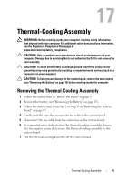
Dell Inspiron N5110 Service Manual - Page 80
Replacing the Processor Module
 |
View all Dell Inspiron N5110 manuals
Add to My Manuals
Save this manual to your list of manuals |
Page 80 highlights
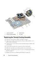
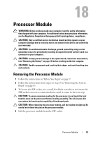
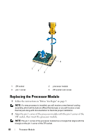
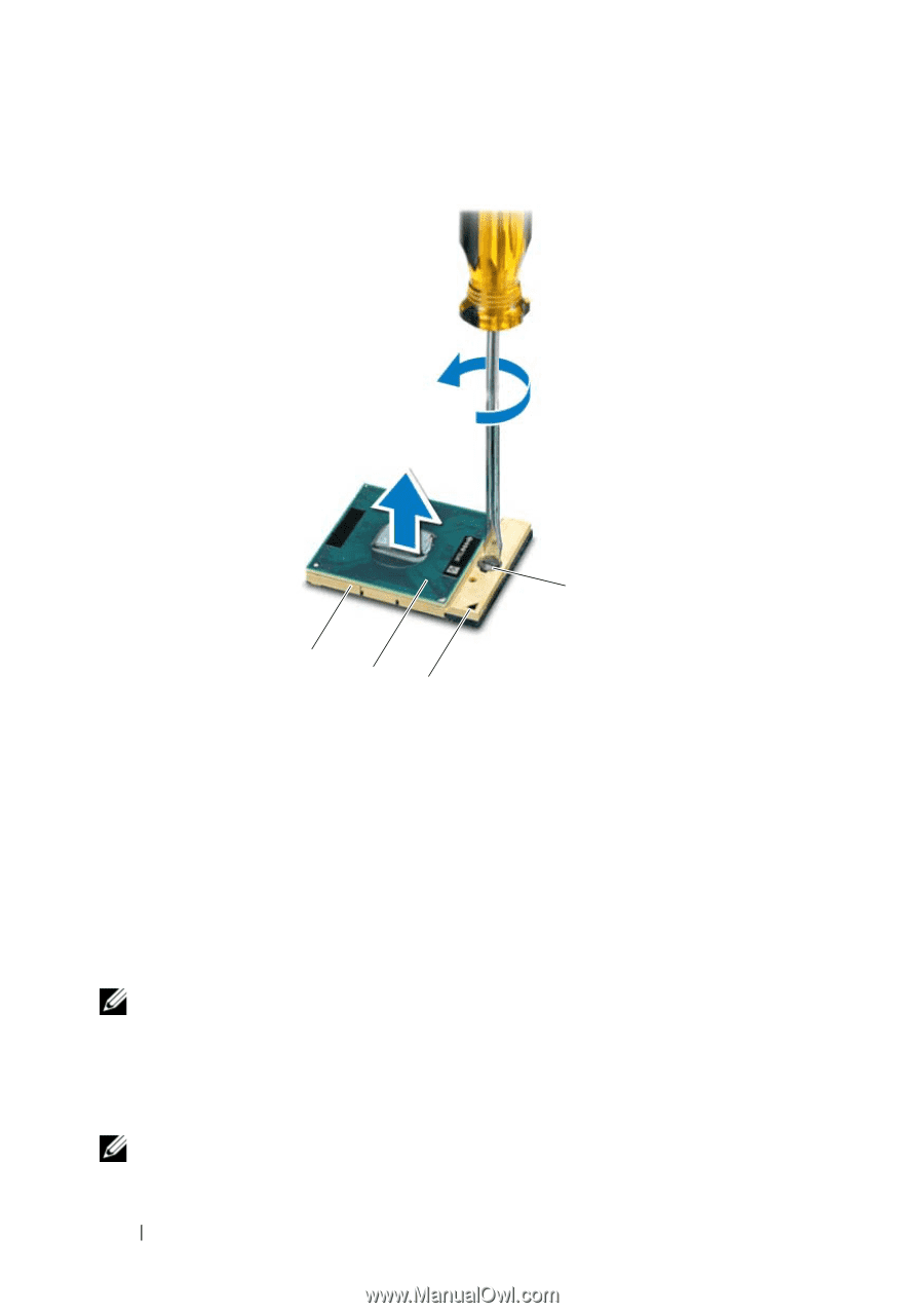
4 1 2 3 1 ZIF socket 3 pin-1 corner 2 processor module 4 ZIF-socket cam screw Replacing the Processor Module 1 Follow the instructions in "Before You Begin" on page 9. NOTE: If a new processor is installed, you will receive a new thermal-cooling assembly, which will include an affixed thermal pad, or you will receive a new thermal pad along with documentation to illustrate proper installation. 2 Align the pin-1 corner of the processor module with the pin-1 corner of the ZIF socket, then insert the processor module. NOTE: The pin-1 corner of the processor module has a triangle that aligns with the triangle on the pin-1 corner of the ZIF socket. 80 Processor Module
-
 1
1 -
2
-
3
-
4
-
5
-
6
-
7
-
8
-
9
-
10
-
11
-
12
-
13
-
14
-
15
-
16
-
17
-
18
-
19
-
20
-
21
-
22
-
23
-
24
-
25
-
26
-
27
-
28
-
29
-
30
-
31
-
32
-
33
-
34
-
35
-
36
-
37
-
38
-
39
-
40
-
41
-
42
-
43
-
44
-
45
-
46
-
47
-
48
-
49
-
50
-
51
-
52
-
53
-
54
-
55
-
56
-
57
-
58
-
59
-
60
-
61
-
62
-
63
-
64
-
65
-
66
-
67
-
68
-
69
-
70
-
71
-
72
-
73
-
74
-
 75
75 -
 76
76 -
 77
77 -
 78
78 -
 79
79 -
 80
80 -
 81
81 -
 82
82 -
 83
83 -
 84
84 -
 85
85 -
86
-
87
-
88
-
89
-
90
 |
 |
80
Processor Module
Replacing the Processor Module
1
Follow the instructions in "Before You Begin" on page 9.
NOTE:
If a new processor is installed, you will receive a new thermal-cooling
assembly, which will include an affixed thermal pad, or you will receive a new
thermal pad along with documentation to illustrate proper installation.
2
Align the pin-1 corner of the processor module with the pin-1 corner of the
ZIF socket, then insert the processor module.
NOTE:
The pin-1 corner of the processor module has a triangle that aligns with the
triangle on the pin-1 corner of the ZIF socket.
1
ZIF socket
2
processor module
3
pin-1 corner
4
ZIF-socket cam screw
1
2
4
3