Dell Inspiron N5110 Service Manual - Page 47
Replacing the Display Panel
 |
View all Dell Inspiron N5110 manuals
Add to My Manuals
Save this manual to your list of manuals |
Page 47 highlights
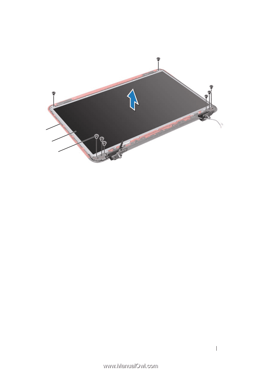
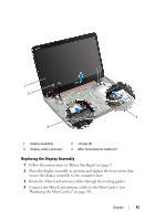
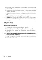
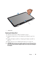
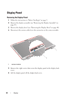
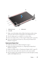
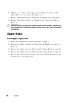
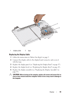
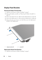
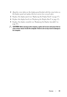
1 2 3 1 display back cover 3 screws (8) 2 display panel 7 Make a note of the display cable and Mini-Card antenna cables routing and remove them from the routing guides on the display back cover. 8 Turn the display panel over and place it on a clean surface. 9 Remove the display cable (see "Removing the Display Cable" on page 48). 10 Remove the display-panel brackets (see "Removing the Display-Panel Brackets" on page 50). Replacing the Display Panel 1 Follow the instructions in "Before You Begin" on page 9. 2 Replace the display-panel brackets (see "Replacing the Display-Panel Brackets" on page 50). 3 Replace the display cable (see "Replacing the Display Cable" on page 49). 4 Connect the camera cable to the connector on the camera module. 5 Route the display cable and Mini-Card antenna cables through the routing guides on the display back cover. Display 47
-
 1
1 -
2
-
3
-
4
-
5
-
6
-
7
-
8
-
9
-
10
-
11
-
12
-
13
-
14
-
15
-
16
-
17
-
18
-
19
-
20
-
21
-
22
-
23
-
24
-
25
-
26
-
27
-
28
-
29
-
30
-
31
-
32
-
33
-
34
-
35
-
36
-
37
-
38
-
39
-
40
-
41
-
 42
42 -
 43
43 -
 44
44 -
 45
45 -
 46
46 -
 47
47 -
 48
48 -
 49
49 -
 50
50 -
 51
51 -
 52
52 -
53
-
54
-
55
-
56
-
57
-
58
-
59
-
60
-
61
-
62
-
63
-
64
-
65
-
66
-
67
-
68
-
69
-
70
-
71
-
72
-
73
-
74
-
75
-
76
-
77
-
78
-
79
-
80
-
81
-
82
-
83
-
84
-
85
-
86
-
87
-
88
-
89
-
90
 |
 |