Dell Latitude D630 Service Manual - Page 14
Removing the Display Panel Brackets, Removing the Display Panel Cable
 |
UPC - 683728230456
View all Dell Latitude D630 manuals
Add to My Manuals
Save this manual to your list of manuals |
Page 14 highlights
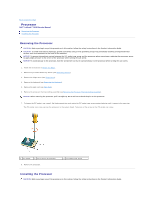
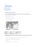
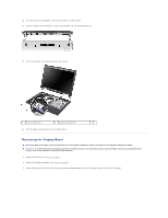
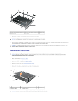
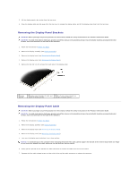
5. Lift the display panel a few inches from the top cover. 6. Draw the display cable pull-tab away from the top cover to release the display cable, and lift the display panel fully from the top cover. Removing the Display Panel Brackets CAUTION: Before you begin any of the procedures in this section, follow the safety instructions in the Product Information Guide. CAUTION: To avoid electrostatic discharge, ground yourself by using a wrist grounding strap or by periodically touching an unpainted metal surface, such as a connector on the back of the computer. 1. Follow the instructions in Before You Begin. 2. Remove the display assembly (see Display Assembly). 3. Remove the display bezel (see Removing the Display Bezel). 4. Remove the display panel (see Removing the Display Panel). 5. Remove the four M2 x 3-mm screws from each side of the display panel. 1 display panel 2 display panel brackets (2) (left and 3 M2 x 3-mm screws (4 each on right of display panel) sides of display panel) Removing the Display Panel Cable CAUTION: Before you begin any of the procedures in this section, follow the safety instructions in the Product Information Guide. CAUTION: To avoid electrostatic discharge, ground yourself by using a wrist grounding strap or by periodically touching an unpainted metal surface, such as a connector on the back of the computer. 1. Follow the instructions in Before You Begin. 2. Remove the display assembly (see Display Assembly). 3. Remove the display bezel (see Removing the Display Bezel). 4. Remove the display panel (see Removing the Display Panel). 5. Turn over the display panel and place it on a clean surface. NOTICE: To avoid damage to the computer when replacing the bottom flex cable, gently support the bottom of the inverter board with one finger as you reseat the bottom flex-cable connector. Do not bend the inverter board. 6. Gently pull the pull-tab on the bottom flex-cable connector to release the cable from the inverter board. 7. Squeeze the flex-cable release levers at either side of the top flex-cable connector to release the connector.
-
 1
1 -
2
-
3
-
4
-
5
-
6
-
7
-
8
-
 9
9 -
 10
10 -
 11
11 -
 12
12 -
 13
13 -
 14
14 -
 15
15 -
 16
16 -
 17
17 -
 18
18 -
 19
19 -
20
-
21
-
22
-
23
-
24
-
25
-
26
-
27
-
28
-
29
-
30
-
31
-
32
-
33
-
34
-
35
-
36
-
37
-
38
-
39
-
40
-
41
-
42
-
43
 |
 |
