Dell M6700 Owner's Manual - Page 45
Removing the Input/Output (I/O) Board, After Working Inside Your Computer.
 |
View all Dell M6700 manuals
Add to My Manuals
Save this manual to your list of manuals |
Page 45 highlights
e) primary and secondary hard drive f) optical drive g) keyboard h) keyboard trim i) base cover j) battery 4. Follow the procedures in After Working Inside Your Computer. Removing the Input/Output (I/O) Board 1. Follow the procedures in Before Working Inside Your Computer. 2. Remove the: a) SD card b) battery c) base cover d) keyboard trim e) keyboard f) optical drive g) primary and secondary hard drive h) palmrest 3. Disconnect the ExpressCard module connector from the system board. 4. Remove the screws that secure the I/O board to the computer. Lift the right edge of the I/O board upwards to disengage the connector and remove it from computer. 45
-
 1
1 -
2
-
3
-
4
-
5
-
6
-
7
-
8
-
9
-
10
-
11
-
12
-
13
-
14
-
15
-
16
-
17
-
18
-
19
-
20
-
21
-
22
-
23
-
24
-
25
-
26
-
27
-
28
-
29
-
30
-
31
-
32
-
33
-
34
-
35
-
36
-
37
-
38
-
39
-
 40
40 -
 41
41 -
 42
42 -
 43
43 -
 44
44 -
 45
45 -
 46
46 -
 47
47 -
 48
48 -
 49
49 -
 50
50 -
51
-
52
-
53
-
54
-
55
-
56
-
57
-
58
-
59
-
60
-
61
-
62
-
63
-
64
-
65
-
66
-
67
-
68
-
69
-
70
-
71
-
72
-
73
-
74
-
75
-
76
-
77
-
78
-
79
-
80
-
81
-
82
-
83
 |
 |

e)
primary and secondary hard drive
f)
optical drive
g)
keyboard
h)
keyboard trim
i)
base cover
j)
battery
4.
Follow the procedures in
After Working Inside Your Computer.
Removing the Input/Output (I/O) Board
1.
Follow the procedures in
Before Working Inside Your Computer
.
2.
Remove the:
a)
SD card
b)
battery
c)
base cover
d)
keyboard trim
e)
keyboard
f)
optical drive
g)
primary and secondary hard drive
h)
palmrest
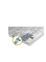
3.
Disconnect the ExpressCard module connector from the system board.
4.
Remove the screws that secure the I/O board to the computer. Lift the right edge of the I/O board upwards to
disengage the connector and remove it from computer.
45