Dell M6700 Owner's Manual - Page 55
Removing the Power-Connector Port - ports
 |
View all Dell M6700 manuals
Add to My Manuals
Save this manual to your list of manuals |
Page 55 highlights
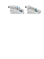
a) switch board b) power connector c) LVDS d) camera e) coin-cell battery f) processor fan 4. Install all the mini-cards (if available). 5. Place the LVDS cable bracket in its original position on the computer and tighten the screw to secure it to the computer. 6. Install the: a) I/O board b) video card c) video-card heat sink. d) processor e) heatsink f) palmrest g) video-card fan h) secondary memory i) primary memory j) primary and secondary hard drive k) optical drive l) keyboard m) keyboard trim n) base cover o) battery p) ExpressCard q) SD card 7. Follow the procedures in After Working Inside Your Computer. Removing the Power-Connector Port 1. Follow the procedures in Before Working Inside Your Computer. 2. Remove the: a) battery b) base cover c) keyboard trim d) keyboard e) optical drive f) primary and secondary hard drive g) palmrest h) I/O board i) display assembly 3. Disconnect the power-connector cable from the system board and remove the power connector port from the computer. 55
-
 1
1 -
2
-
3
-
4
-
5
-
6
-
7
-
8
-
9
-
10
-
11
-
12
-
13
-
14
-
15
-
16
-
17
-
18
-
19
-
20
-
21
-
22
-
23
-
24
-
25
-
26
-
27
-
28
-
29
-
30
-
31
-
32
-
33
-
34
-
35
-
36
-
37
-
38
-
39
-
40
-
41
-
42
-
43
-
44
-
45
-
46
-
47
-
48
-
49
-
 50
50 -
 51
51 -
 52
52 -
 53
53 -
 54
54 -
 55
55 -
 56
56 -
 57
57 -
 58
58 -
 59
59 -
 60
60 -
61
-
62
-
63
-
64
-
65
-
66
-
67
-
68
-
69
-
70
-
71
-
72
-
73
-
74
-
75
-
76
-
77
-
78
-
79
-
80
-
81
-
82
-
83
 |
 |
