Dell N3200-ON External Power Supply Installation PowerSwitch N2200-ON and N320 - Page 10
Important information, About Notes, Cautions, Warnings, Installation, Console and Ethernet ports
 |
View all Dell N3200-ON manuals
Add to My Manuals
Save this manual to your list of manuals |
Page 10 highlights
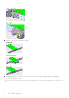
6. Install four wall-mount anchors into the four holes. 7. Screw four M5 screws into the four wall-mount anchors leaving approximately 0.20 in (5 mm) gap between the anchor and the screw. 8. Slide the EPS onto the screws and tighten the screws to secure the EPS in place. Torque the screws to 24 in-lbs. Important information The following is information that you must have to safely use the EPS: About Notes, Cautions, Warnings NOTE: A NOTE indicates important information that helps you make better use of your product. CAUTION: A CAUTION indicates either potential damage to hardware or loss of data and tells you how to avoid the problem. WARNING: A WARNING indicates a potential for property damage, personal injury, or death. Installation WARNING: This equipment must be earthed. Connect the power plug to a properly wired earth ground socket outlet. NOTE: Install the switch equipment in restricted access areas. A restricted access area is one in which service personnel can only gain access using a special tool, lock, key or other means of security. The authority responsible for the location controls access to the restricted area. Console and Ethernet ports The Console and Ethernet ports are used for debugging and firmware updates by service personnel only, and are not available for use to the end user. Ground cable To attach a ground cable to the switch, use the included M4 screws (length 6.8 mm). The ground cable is not included. The grounding lugs must be a UL-recognized, crimp-type lug. CAUTION: Grounding conductors must be made of copper. Do not use aluminum conductors. 10 N-Series EPS installation
-
 1
1 -
2
-
3
-
4
-
 5
5 -
 6
6 -
 7
7 -
 8
8 -
 9
9 -
 10
10 -
 11
11
 |
 |
