Dell N3200-ON External Power Supply Installation PowerSwitch N2200-ON and N320 - Page 9
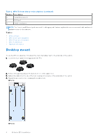
Wall mount locations for MPS-1S are approximately 8.37 in x 6.76 in 212.60 mm x 171.85 mm L x W.
 |
View all Dell N3200-ON manuals
Add to My Manuals
Save this manual to your list of manuals |
Page 9 highlights
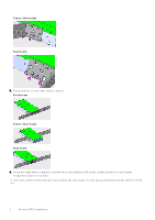
2. Screw two brackets to the left side of the EPS using the M4 screws (length 6.8 mm) for each bracket, as shown. Torque the screws to 10 in-lbs. 3. Repeat to attach two brackets to the right side of the EPS, as shown. 4. Hold the EPS or wall-mount template to the wall and mark the screw-hole locations on the wall with the pencil. Wall mount locations for MPS-1S are approximately 8.37 in x 6.76 in (212.60 mm x 171.85 mm) (L x W). 5. Drill four 0.3 in (8 mm) holes in the wall at the pencil marks. N-Series EPS installation 9
-
 1
1 -
2
-
3
-
 4
4 -
 5
5 -
 6
6 -
 7
7 -
 8
8 -
 9
9 -
 10
10 -
 11
11
 |
 |

2.
Screw two brackets to the left side of the EPS using the M4 screws (length 6.8 mm) for each bracket, as shown.
Torque the screws to 10 in-lbs.
3.
Repeat to attach two brackets to the right side of the EPS, as shown.
4.
Hold the EPS or wall-mount template to the wall and mark the screw-hole locations on the wall with the pencil.
Wall mount locations for MPS-1S are approximately 8.37 in x 6.76 in (212.60 mm x 171.85 mm) (L x W).
5.
Drill four 0.3 in (8 mm) holes in the wall at the pencil marks.
N-Series EPS installation
9