Dell N3200-ON External Power Supply Installation PowerSwitch N2200-ON and N320 - Page 4
Desktop mount
 |
View all Dell N3200-ON manuals
Add to My Manuals
Save this manual to your list of manuals |
Page 4 highlights
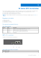
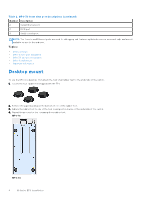
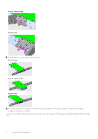
Table 2. MPS-3S front view port descriptions (continued) Number Description 2 Serial Ethernet port 3 RJ45 port 4 Serial console port NOTE: The Console and Ethernet ports are used for debugging and firmware updates by service personnel only, and are not available for use to the end user. Topics: • Desktop mount • MPS-1S two-post installation • MPS-3S two-post installation • MPS-1S wall mount • Important information Desktop mount To use the EPS on a desktop, first attach the four small rubber feet to the underside of the switch. 1. Locate the four rubber feet shipped with the EPS. 2. Remove the paper backing on the bottom of one of the rubber feet. 3. Adhere the rubber foot to one of the four round position marks on the underside of the switch. 4. Repeat the process for the remaining three rubber feet. MPS-1S: MPS-3S 4 N-Series EPS installation
-
 1
1 -
 2
2 -
 3
3 -
 4
4 -
 5
5 -
 6
6 -
 7
7 -
 8
8 -
 9
9 -
 10
10 -
11
 |
 |
