Dell OptiPlex 380 Service Manual - Page 40
System Board Layout
 |
View all Dell OptiPlex 380 manuals
Add to My Manuals
Save this manual to your list of manuals |
Page 40 highlights
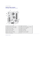
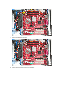
Back to Contents Page System Board Layout Dell™ OptiPlex™ 380 Service Manual-Mini-Tower 1 speaker connector (INT_SPKR) 3 processor power connector (12V POWER) 5 SATA drive connectors (SATA0 and SATA1) 7 power connector (POWER) 9 intruder connector (INTRUDER) 11 password jumper (PSWD) 13 coin-cell battery socket (BATTERY) 15 PCI connectors (SLOT2 and SLOT3) 17 fan connector (FAN_CPU) Back to Contents Page 2 processor connector (CPU) 4 memory module connectors (DIMM_1 and DIMM_2) 6 front-panel connector (FRONTPANEL) 8 SATA drive connector (SATA2) 10 reset jumper (RTCRST) 12 internal speaker (SPKR) 14 PCI Express x16 connector (SLOT1) 16 serial/ PS/2 connector (PS2/SER2)
-
 1
1 -
2
-
3
-
4
-
5
-
6
-
7
-
8
-
9
-
10
-
11
-
12
-
13
-
14
-
15
-
16
-
17
-
18
-
19
-
20
-
21
-
22
-
23
-
24
-
25
-
26
-
27
-
28
-
29
-
30
-
31
-
32
-
33
-
34
-
 35
35 -
 36
36 -
 37
37 -
 38
38 -
 39
39 -
 40
40 -
 41
41 -
 42
42 -
 43
43 -
 44
44 -
 45
45 -
46
-
47
-
48
-
49
-
50
-
51
-
52
-
53
-
54
 |
 |

Back to Contents Page
System Board Layout
Dell™ OptiPlex™ 380 Service Manual—
Mini-Tower
Back to Contents Page
1
speaker connector (INT_SPKR)
2
processor connector (CPU)
3
processor power connector (12V POWER)
4
memory module connectors (DIMM_1 and DIMM_2)
5
SATA drive connectors (SATA0 and SATA1)
6
front-panel connector (FRONTPANEL)
7
power connector (POWER)
8
SATA drive connector (SATA2)
9
intruder connector (INTRUDER)
10
reset jumper (RTCRST)
11
password jumper (PSWD)
12
internal speaker (SPKR)
13
coin-cell battery socket (BATTERY)
14
PCI Express x16 connector (SLOT1)
15
PCI connectors (SLOT2 and SLOT3)
16
serial/ PS/2 connector (PS2/SER2)
17
fan connector (FAN_CPU)