Dell Precision M65 Dell Precision M65 Mobile Workstation Service Manual - Page 10
Processor Module - service manual
 |
View all Dell Precision M65 manuals
Add to My Manuals
Save this manual to your list of manuals |
Page 10 highlights
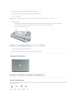
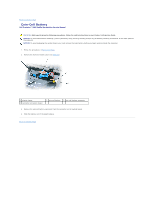
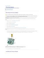
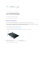
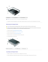
Back to Contents Page Processor Module Dell Precision™ M65 Mobile Workstation Service Manual Removing the Processor Module Installing the Processor Module Removing the Processor Module CAUTION: Before performing the following procedures, follow the safety instructions in the Product Information Guide. CAUTION: To prevent static damage to components inside your computer, discharge static electricity from your body before you touch any of your computer's electronic components. You can do so by touching an unpainted metal surface. NOTICE: Press and hold the processor down by applying slight pressure to the center of the processor while turning the cam screw to prevent intermittent contact between the cam screw and processor. NOTICE: To avoid damage to the processor, hold the screwdriver so that it is perpendicular to the processor when turning the cam screw. 1. Follow the instructions in Before Working Inside Your Computer. 2. Remove the hinge cover (see Hinge Cover). 3. Remove the keyboard (see Keyboard). 4. Remove the display assembly (see Display Assembly). 5. Remove the palm rest (see Palm Rest). 6. Remove the processor thermal-cooling assembly (see Processor Thermal-Cooling Assembly). NOTICE: When removing the processor module, pull the module straight up. Be careful not to bend the pins on the processor module. 7. To loosen the ZIF socket, use a small, flat-blade screwdriver and rotate the ZIF-socket cam screw counterclockwise until it comes to the cam stop. The ZIF-socket cam screw secures the processor to the system board. Take note of the arrow on the ZIF-socket cam screw. 1 ZIF-socket 2 ZIF-socket cam screw 3 pin-1 corner of processor 8. Use a processor extraction tool to remove the processor module. Installing the Processor Module
-
 1
1 -
2
-
3
-
4
-
 5
5 -
 6
6 -
 7
7 -
 8
8 -
 9
9 -
 10
10 -
 11
11 -
 12
12 -
 13
13 -
 14
14 -
 15
15 -
16
-
17
-
18
-
19
-
20
-
21
-
22
-
23
-
24
-
25
-
26
-
27
-
28
-
29
-
30
-
31
-
32
-
33
-
34
-
35
-
36
-
37
-
38
-
39
 |
 |