Denon DCM 390 Serial Protocol - Page 3
Serial communication interface, Physical interface
 |
UPC - 081757506991
View all Denon DCM 390 manuals
Add to My Manuals
Save this manual to your list of manuals |
Page 3 highlights
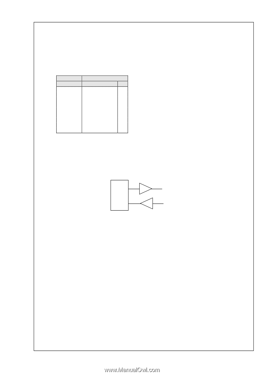
Revision1.40 Date 24.May.'07 1 Serial communication interface DCM390 Serial Interface Specification 3 page of 40 1.1 Physical interface a) DCM280 has pin Dsub female connector for serial interface. b) Table 1 indicates pin assignment of connector signals. Terminal # 1 2 3 4 5 6 7 8 9 RS-232C Signal I/O NC - TxD O RxD I NC - S.GROUND - NC - NC - NC - NC - Table 1. Pin Assignment c) Figure 1 indicates diagram of RS232C and RS422A. RS-232C CPU TXD RXD Figure 1. Serial Driver/Receiver D&M
-
 1
1 -
 2
2 -
 3
3 -
 4
4 -
 5
5 -
 6
6 -
 7
7 -
 8
8 -
 9
9 -
10
-
11
-
12
-
13
-
14
-
15
-
16
-
17
-
18
-
19
-
20
-
21
-
22
-
23
-
24
-
25
-
26
-
27
-
28
-
29
-
30
-
31
-
32
-
33
-
34
-
35
-
36
-
37
-
38
-
39
-
40
 |
 |
Revision1.40
DCM390 Serial Interface Specification
Date 24.May.’07
3 page of 40
1
Serial communication interface
1.1
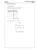
Physical interface
a)
DCM280 has pin Dsub female connector for serial interface.
b)
Table 1 indicates pin assignment of connector signals.
RS-232C
Terminal #
Signal
I/O
1
NC
-
2
TxD
O
3
RxD
I
4
NC
-
5
S.GROUND
-
6
NC
-
7
NC
-
8
NC
-
9
NC
-
Table 1. Pin Assignment
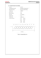
c)
Figure 1 indicates diagram of RS232C and RS422A.
RS-232C
Figure 1. Serial Driver/Receiver
CPU
TXD
RXD