EMC DS-5100B Hardware Reference - Page 20
Electrical considerations, Environmental considerations, Cabinet considerations
 |
View all EMC DS-5100B manuals
Add to My Manuals
Save this manual to your list of manuals |
Page 20 highlights
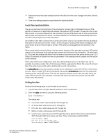
2 Installation and safety considerations Electrical considerations To install and operate the switch successfully, ensure the following: • The primary outlet is correctly wired, protected by a circuit breaker, and grounded in accordance with local electrical codes. • The supply circuit, line fusing, and wire size are adequate, as specified by the electrical rating on the switch nameplate. • The power supply standards provided in Table 5, "Power Supply Specifications" on page 28 are met. Environmental considerations For successful installation and operation of the switch, ensure that the following environmental requirements are met: • At a minimum, adequate cooling requires that you install the switch with the non-port side, which contains the air intake vents, facing the cool-air aisle. • All equipment in the rack should force air in the same direction to avoid intake of exhaust air. • A maximum of 49.3 cubic meters/hour (29 cubic feet/minute) and a minimum of 37.4 cubic meters/hour (22 cubic feet/minute) of air flow is available to the air intake vents on the non-port side of the switch. • The ambient air temperature does not exceed 40° C (104° F) while the switch is operating. Cabinet considerations For successful installation and operation of the switch in a cabinet, ensure the following cabinet requirements are met: • The cabinet must be a standard EIA cabinet. • Plan a cabinet space that is one rack unit (1U) high; 4.45 cm (1.75 inches) and 48.3 cm (19 inches) wide. • Ground all equipment in the cabinet through a reliable branch circuit connection and maintain ground at all times. Do not rely on a secondary connection to a branch circuit, such as a power strip. • Ensure that airflow and temperature requirements are met on an ongoing basis, particularly if the switch is installed in a closed or multicabinet assembly. • Verify that the additional weight of the switch does not exceed the cabinet's weight limits or unbalance the cabinet in any way. • Secure the cabinet to ensure stability in case of unexpected movement, such as an earthquake. Recommendations for cable management The minimum bend radius for a 50 micron cable is 2 inches under full tensile load and 1.2 inches with no tensile load. 8 Brocade 5100 Hardware Reference Manual 53-1000854-02
-
 1
1 -
2
-
3
-
4
-
5
-
6
-
7
-
8
-
9
-
10
-
11
-
12
-
13
-
14
-
 15
15 -
 16
16 -
 17
17 -
 18
18 -
 19
19 -
 20
20 -
 21
21 -
 22
22 -
 23
23 -
 24
24 -
 25
25 -
26
-
27
-
28
-
29
-
30
-
31
-
32
-
33
-
34
-
35
-
36
-
37
-
38
-
39
-
40
-
41
-
42
-
43
-
44
-
45
-
46
-
47
-
48
-
49
-
50
-
51
-
52
-
53
-
54
 |
 |
