EMC DS-5100B Hardware Reference - Page 29
Brocade 5100 Operation, In this Powering the Brocade 5100 on and off
 |
View all EMC DS-5100B manuals
Add to My Manuals
Save this manual to your list of manuals |
Page 29 highlights
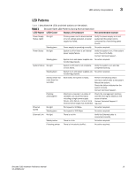
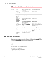
Brocade 5100 Operation Chapter 3 In this chapter •Powering the Brocade 5100 on and off 17 •LED activity interpretation 17 •POST and boot specifications 20 •Interpreting POST results 21 •Maintaining the Brocade 5100 21 •Managing the Brocade 5100 24 Powering the Brocade 5100 on and off To power the Brocade 5100 on, connect one or both power cords to the power connectors on the power supplies and to a power source; then, set the AC power switches to "I". Power is supplied to the switch as soon as the first power supply is connected and powered on. The switch runs POST by default each time it is powered on; it can take up to several minutes to boot and complete POST. To power the Brocade 5100 off, power off both power supplies by setting each AC power switch to "O". All devices are returned to their initial state the next time the switch is powered on. LED activity interpretation System activity and status can be determined through the activity of the LEDs on the switch. There are three possible LED states: no light, a steady light, and a flashing light. The lights are green or amber. Sometimes, the LEDs flash either of the colors during boot, POST, or other diagnostic tests. This is normal; it does not indicate a problem unless the LEDs do not indicate a healthy state after all boot processes and diagnostic tests are complete. Brocade 5100 LEDs The Brocade 5100 has the following LEDs: • One system status LED (above) on the left side • One power status LED (below) on the left side • 40 port status LEDs, one for each Fibre Channel port, located above the ports • One power supply status LED on each power supply FRU, to the left of the ON/OFF rocker switch on the non-port side of the switch Brocade 5100 Hardware Reference Manual 17 53-1000854-02
-
 1
1 -
2
-
3
-
4
-
5
-
6
-
7
-
8
-
9
-
10
-
11
-
12
-
13
-
14
-
15
-
16
-
17
-
18
-
19
-
20
-
21
-
22
-
23
-
 24
24 -
 25
25 -
 26
26 -
 27
27 -
 28
28 -
 29
29 -
 30
30 -
 31
31 -
 32
32 -
 33
33 -
 34
34 -
35
-
36
-
37
-
38
-
39
-
40
-
41
-
42
-
43
-
44
-
45
-
46
-
47
-
48
-
49
-
50
-
51
-
52
-
53
-
54
 |
 |
