EMC DS-5100B Hardware Reference - Page 35
Field Replaceable Units (FRUs), Power supply/fan assembly FRU replacement
 |
View all EMC DS-5100B manuals
Add to My Manuals
Save this manual to your list of manuals |
Page 35 highlights
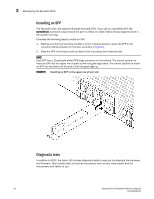
Maintaining the Brocade 5100 3 The tests are implemented by command, either through a Telnet session or through a terminal set up for a serial connection to the switch. Some tests require the ports to be connected by external cables, to allow diagnostics to verify the serializer/deserializer interface, transceiver, and cable. Some tests require loopback plugs. Diagnostic tests are run at link speeds of 1, 2, 4, and 8 Gbps depending on the speed of the link being tested. NOTE Diagnostic tests might temporarily lock the transmit and receive speed of the links during diagnostic testing. For information about specific diagnostic tests, refer to the Fabric OS Troubleshooting and Diagnostics Guide. Field Replaceable Units (FRUs) The power supplies have the fans inside and can be replaced onsite without the use of special tools. The power supply/fan assembly units are keyed to ensure correct orientation during installation. Replacement instructions are provided with all replacement units ordered. Power supply/fan assembly FRU replacement The Brocade 5100 fans are fixed inside the integrated power supply/fan FRU to provide necessary airflow to cool the whole system. There is one fan located in the rear section of each FRU. The system software sets fan speed and measures their speeds through the tachometer interface. The two power supply/fan assembly FRU units are hot-swappable if replaced one at a time. They are identical and fit into either slot. Fabric OS identifies the power supplies as follows (viewing the switch from the port side): • Power supply #1 is on the left • Power supply #2 is on the right Determining power supply/fan replacement need 1. Use one of the following methods to determine whether a power supply requires replacement: • Check the power supply status LED next to the I/O switch. If the power supply status LED is not on, verify that the power supply is on and seated and the power cord is connected to a functioning power source. If the light does not turn green, the power supply needs to be replaced. • In Web Tools, click the Power Status icon. • Type the psShow command at the command prompt to display power supply status as shown below: switch:admin> psshow Power Supply #1 is OK Power Supply #2 is OK Brocade 5100 Hardware Reference Manual 23 53-1000854-02
-
 1
1 -
2
-
3
-
4
-
5
-
6
-
7
-
8
-
9
-
10
-
11
-
12
-
13
-
14
-
15
-
16
-
17
-
18
-
19
-
20
-
21
-
22
-
23
-
24
-
25
-
26
-
27
-
28
-
29
-
 30
30 -
 31
31 -
 32
32 -
 33
33 -
 34
34 -
 35
35 -
 36
36 -
 37
37 -
 38
38 -
 39
39 -
 40
40 -
41
-
42
-
43
-
44
-
45
-
46
-
47
-
48
-
49
-
50
-
51
-
52
-
53
-
54
 |
 |
