Epson 2080 Service Manual
Epson 2080 - LQ B/W Dot-matrix Printer Manual
 |
View all Epson 2080 manuals
Add to My Manuals
Save this manual to your list of manuals |
Epson 2080 manual content summary:
- Epson 2080 | Service Manual - Page 1
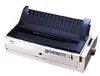
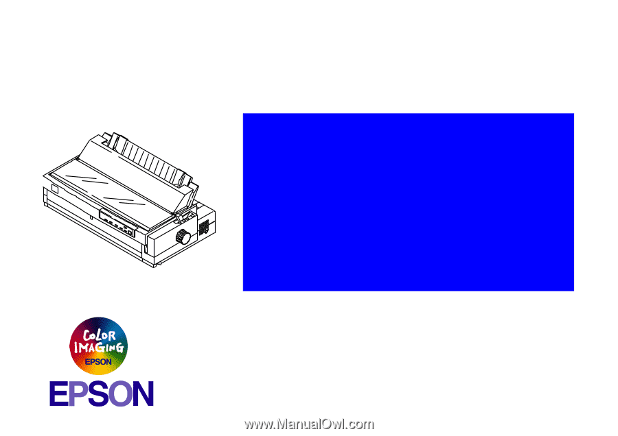
Impact Serial Dot Matrix Printer EPSON LQ-2080 ® SEDM98002 - Epson 2080 | Service Manual - Page 2
reserved. No part of this manual may be reproduced, stored in a retrieval system, or transmitted in any form or by any means, electronic, mechanical, photocopying, recording, or otherwise, without the prior written permission of SEIKO EPSON CORPORATION. The contents of this manual are subject to - Epson 2080 | Service Manual - Page 3
in performing procedures preceded by DANGER Headings. WARNING Signals a precaution which, AS DICTATED WITHIN THIS MANUAL, DO NOT CONNECT THE UNIT TO A POWER SOURCE UNTIL INSTRUCTED TO DO SO. THE EPSON PRODUCT HAS BEEN DISCONNECTED FROM THE POWER SOURCE BEFORE REMOVING OR REPLACING PRINTED CIRCUIT - Epson 2080 | Service Manual - Page 4
PREFACE This manual describes basic functions, theory of electrical and mechanical operations, maintenance and repair procedures of EPSON LQ-2080. The instructions and procedures included herein are intended for the experienced repair technicians, and attention should be given to the precautions on - Epson 2080 | Service Manual - Page 5
Revision A Revision Status Issued Date March 08, 1999 Description First release - Epson 2080 | Service Manual - Page 6
15 Operation Instruction 16 Errors ...17 EEPROM Initialization 18 Main Components 19 C273 Main Board 20 Operating Principles Printer Mechanism Operations 22 Power Supply Operation 22 Control Circuit 23 Overview of Control Circuit Operation 23 System Reset Circuit 25 Printhead Driver Circuit - Epson 2080 | Service Manual - Page 7
PRODUCT DESCRIPTION - Epson 2080 | Service Manual - Page 8
Self-Test, Data Dump, and the Default Setting * : Mean print volume between failure (MTBF 25% duty cycle) 1.1.2 Accessories Table 1-1. Items Included with the Printer Enclosed Items Quantity User's manual 1 Driver diskette 1 Ribbon cartridge 1 Power supply cable (230 V Version) 1 Table - Epson 2080 | Service Manual - Page 9
information specific to the LQ-2080. For other information, refer to the LQ-2070 Service Manual. 1.2.1 Printing Method See the LQ-2070 Service Manual. 1.2.2 Printing Specifications Copy capability: 1 original + 4 copies Print speed and printable columns Table 1-3. Print Speed and Printable - Epson 2080 | Service Manual - Page 10
LQ-2080 Release lever: See the following table. Table 1-4. Release Lever Settings Lever Position Paper path / Feeder Paper / Media Manual insertion (front) Cut sheet (Single sheet & Multi part), Card Friction Manual insertion (rear) CSF Bin 1 Cut sheet (Single sheet & Multi part 10 - Epson 2080 | Service Manual - Page 11
LQ-2080 > 7.8 inch 200 mm 1.2.5 Ribbon Specificatio Ribbon life: Approximately 8 million characters (LQ 10 cpi, 48 dots / character) LQ-2070 Service Manual. 1.2.8 Reliability MVBF *: MTBF: Printhead life: 19 million lines (except printhead) 10000 POH 200 million strokes/wire *: Mean print - Epson 2080 | Service Manual - Page 12
LQ-2080 1.2.9 Safety Approvals 120 V version Safety standards: UL1950, CSA C22.2 No. 950 EMI: FCC part15 subpart B class B CSA C108.8 class B 230 V version Safety standards: EN60950 (TUV) EMI: EN55022 (CISPR pub.22) class B AS/NZS 3548 class B 1.2.10 CE Marking 230 V version Low voltage - Epson 2080 | Service Manual - Page 13
1.3 Firmware Specifications This section describes the firmware specifications for the LQ-2080. 1.3.1 Control Codes and Fonts Control codes: ESC/P2 and IBM 2391 Plus Emulation Character tables: Standard version (13 character tables) Italic table PC 860 (Portuguese) PC 850 (Multilingual) PC - Epson 2080 | Service Manual - Page 14
LQ-2080 Revision A Table 1-6. Character Tables and Available Typefaces Character Tables Bit map font Scaleable EPSON Draft (Arabic) EPSON Roman EPSON Sans Serif (Not supported) Hebrew7*2 Hebrew 8*2 PC862 (Hebrew)*2 EPSON Draft (Hebrew) EPSON Roman (Not supported) EPSON Courier *1: ESC - Epson 2080 | Service Manual - Page 15
is specific to the LQ-2080. For other information, refer to the LQ-2070 Service Manual. 1.3.2.1 Parallel Interface ( ] MFG: EPSON; CMD: ESCPL2,PRPXL24,BDC; MDL: LQ-2080; CLS: PRINTER; DES: EPSON[SP]LQ-2080; Pin assignment: The pin assignment (reverse channel) is the same as for the LQ-2070 except - Epson 2080 | Service Manual - Page 16
of the control panel are mostly common to those of LQ-2070, this section only provides the information that is specific to LQ-2080. For other information, see LQ2070 Service Manual. Operations at power on Turning on the printer while pressing panel buttons executes the functions shown in the - Epson 2080 | Service Manual - Page 17
LQ-2080 Status code indicated by the LEDs Table 1-9. Status Code Indicated by the LEDs Pause Paper Out Tear Off / Bin Condensed Pause On --- --- --- Paper out error On On --- --- Paper eject warning On Blink --- --- Head Paper out: When printer fails to feed a Instruction 17 - Epson 2080 | Service Manual - Page 18
TOF adjustment value (front manual insertion) 8.5 mm 12 Bottom margin (rear tractor) 11 inch 13 Bottom margin (front tractor) 11 inch 14 Font selection Roman 15 Condensed Off 16 Print direction setting Bi-D 17 I/F mode selection Auto 18 Auto I/F wait time setting 10 sec 19 Auto line - Epson 2080 | Service Manual - Page 19
main components for the LQ-2080 are as follows. They are designed for easy disassembly and repair work. C273 Main Board C166 PSB/PSE Board C165 PNL Board Printer Mechanism Housing (upper and lower cases) Revision A Product Description Figure 1-1. Main Components for LQ-2080 Main Components 19 - Epson 2080 | Service Manual - Page 20
LQ-2080 1.5.1 C273 Main Board Table 1-12. Relationship between Program ROM and CG Destination Program ROM(IC10) CG ROM(IC6) Comments Standard 8 M bit TDD21 None Standard Character is stored in the Program ROM. Europe 8 M bit TDD25 None Standard Character is stored in the Program ROM. - Epson 2080 | Service Manual - Page 21
OPERATING PRINCIPLES - Epson 2080 | Service Manual - Page 22
LQ-2080 2.1 Printer Mechanism Operations See the LQ-2070 Service Manual. 2.2 Power Supply Operation See the LQ-2070 Service Manual. Revision A Operating Principles Printer Mechanism Operations 22 - Epson 2080 | Service Manual - Page 23
66 MHz, an E05B24YB gate array, a 1M bit PS-RAM (8-bit bus, less than 100ns), a bit PROM (8-bit bus, less than 100ns), CG (Standard Version) or CG (NLSP Version). It oversees control of all the components in the printer. The following chart shows you a block diagram of the control circuit. Revision - Epson 2080 | Service Manual - Page 24
IC 3 • Clock control unit • Bit manipulation • Interface control • Expanded parallel port • Printhead control • Motor control An electrically writable and erasable ROM used to IC 5 hold information such as the TOF position and bidirectional adjustment value. IC 10 The ROM contains the - Epson 2080 | Service Manual - Page 25
LQ-2080 2.3.1 System Reset Circuit Control circuits IC3 and IC4 are initialized when a /RESET signal (LOW level) is output from port 1 (VOUT) of IC2. IC2 monitors the +5 V - Epson 2080 | Service Manual - Page 26
LQ-2080 2.3.2 Printhead Driver Circuit The standard voltage for the A/D converter is made in ZD1 and input to CPU port 78. Based on this standard voltage, the A/D converter in the CPU operates. Port 74 monitors the +35 V line between R139 and R140 to determine the printhead driver pulse width. Using - Epson 2080 | Service Manual - Page 27
LQ-2080 2.3.3 CR Motor Driver Circuit The CR motor driver circuit is shown below. Revision A The carriage motor driver circuit controls the CR motor, using the selected print mode. Table 2-2 in the following page describes the motor driver modes. The SLA7024M (IC11) CR motor driver circuit detects - Epson 2080 | Service Manual - Page 28
LQ-2080 Revision A Speed Mode 4 3 8/3 2 Print Speed (CPS) 400 300 267 200 3/2 150 1 100 (Normal) 1 (copy) 100 3/4 75 2/3 67 1/2 50 1/3 33 1/4 25 1/6 17 Table 2-2. CR Motor Driver Modes Drive Frequency (PPS) Excitation Phase Applications 4800 2-2 High speed draft 7200 1-2 - Epson 2080 | Service Manual - Page 29
LQ-2080 2.3.4 PF Motor Driver Circuit The figure below shows the PF motor driver circuit. Revision A 2.3.5 EEPROM Control Circuit The EEPROM is nonvolatile memory that stores information even if the printer power is off. The figure below shows the EEPROM control circuit. Figure 2-7. PF Motor - Epson 2080 | Service Manual - Page 30
LQ-2080 Revision A 2.3.6 Sensor Circuits The CPU detects conditions of the following sensors: home position (HP) sensor, release sensors 1 and 2, platen gap (PG) sensor, rear and front paper end (PE) sensors, paper width (PW) sensor. Two types of sensors are used in this printer. Release sensors - Epson 2080 | Service Manual - Page 31
DISASSEMBLY AND ASSEMBLY - Epson 2080 | Service Manual - Page 32
LQ-2080 See the LQ-2070 Service Manual. Revision A Disassembly and Assembly 32 - Epson 2080 | Service Manual - Page 33
ADJUSTMENT - Epson 2080 | Service Manual - Page 34
4-1 in the LQ-2170 Service Manual and perform any necessary adjustment after disassembling/assembling the printer. Though the conditions for each adjustment are the same as for the LQ-2070, the adjustment program used for the LQ-2080 is different. Therefore, observe the instructions given in the - Epson 2080 | Service Manual - Page 35
LQ-2080 Revision A Figure 4-2. Destination Selection Screen 8. Check the printer to be adjusted for the destination and press the Enter key. Be sure to select a proper destination. If you select a wrong destination, the printer may not print desirable characters. 9. The following screen appears. - Epson 2080 | Service Manual - Page 36
LQ-2080 4.1.2 Bi-D Adjustment This adjustment is made after the main board or the CR motor has been replaced. The purpose of this adjustment is to electrically correct the head wire's point of impact during Bi-D printing. The adjusted value is stored in the specific address in the EEPROM. Once the - Epson 2080 | Service Manual - Page 37
LQ-2080 Revision A 6. When this adjustment is completed, if you need to perform another adjustment using this program, you can continue without turning off the printer. 4.1.3 TPE Level Reset Make this adjustment when the main board or Top PE Sensor has been replaced. Generally, light level - Epson 2080 | Service Manual - Page 38
LQ-2080 4.1.4 Writing the User-characteristic Data Use this function to check the specific records of the printer used by your customer. Also, you can renew the starting date using this program. Since there is no standardized service operation using this function, you can use it whenever necessary. - Epson 2080 | Service Manual - Page 39
LQ-2080 Figure 4-10. Screen - Setting Starting Year / Month / Date 5. Input a 6-digit data. Be sure to input it correctly since this program does not perform comparison check with the system timer. If you input a wrong data, start from the beginning. Revision A Adjustment Overview 39 - Epson 2080 | Service Manual - Page 40
TROUBLESHOOTING - Epson 2080 | Service Manual - Page 41
gives you troubleshooting information to let you test points for replaceable units. 5.2.1 Printhead The information in this section is the same as for the LQ-2070 except for the point below: Point: Table 5-1 (LQ-2070 Service Manual) Meter Reading 39.3 ± 10% Ω → 29.6 ± 10 - Epson 2080 | Service Manual - Page 42
: Main board number C186 Main Board → C273 Main Board 5.4 Repairing the C166 PSB/PSE Board See LQ-2070 Service Manual. 5.5 Repairing the C273 Main Board This section provides instructions to repair the C273 Main Board assembly. It describes various problems, symptoms, likely - Epson 2080 | Service Manual - Page 43
LQ-2080 Table 5-3. Repairing the C272MAIN Board (2/3) Problem Cause Checkpoint Solution The printer head drive signal is not output, replace IC3 (or replace the main board). If the head drive signal is output from the head drive transistors, replace the head drive transistor. Troubleshooting - Epson 2080 | Service Manual - Page 44
LQ-2080 5.6 Repairing the Printer Mechanism The information for this section is also the same as for the LQ-2070 except for the point below. Point: Table 5-8 (LQ-2070 Service Manual) 39.3 ohms → 29.6 ohms Revision A Troubleshooting Repairing the Printer Mechanism 44 - Epson 2080 | Service Manual - Page 45
MAINTENANCE - Epson 2080 | Service Manual - Page 46
LQ-2080 See the LQ-2070 Service Manual. Revision A Maintenance 46 - Epson 2080 | Service Manual - Page 47
APPENDIX - Epson 2080 | Service Manual - Page 48
LQ-2080 LAT 8: ISO Latin 1 27:PC866 UKR 9: Roman 8 28:Hebrew 7 10:PC437 Greek 29:Hebrew 8 11:PC852 30:PC862 12:PC853 31:PCAPTEC 13:PC855 insertion 0000H 0000H (8.5 mm) (8.5 mm) 16H, 17H TOF adjustment value for front manual insertion -60 to 360 (4.2 mm to 8.5 0000H 0000H mm + 1 inch, - Epson 2080 | Service Manual - Page 49
LQ-2080 Table 7-3. EEPROM Address Map (3/7) Address Data Data Format Q-pit Factory data setting 1DH Condensed 0: Off 1: On 00H (Off) 00H (Off) 1EH (reserved) 1FH Print direction setting 0: Bi-d. 1: Uni-d. 2: Auto 20H I/F mode selection 0: Auto I/F selection 1: Parallel I/F 2: Type-B I/F - Epson 2080 | Service Manual - Page 50
LQ self test 00H 00H 2AH Panel mask pattern 2 b0: LF function b1: FF function b2: Micro Adjust function b3: Pause function b4: Data dump b5: Default setting b6: Bi-d. adjustment b7: (reserved) 00H 00H 2BH Manual 00H 30H-33H Driving line count for ribbon change timing 0 - 0FFFFFFFFH (count) - Epson 2080 | Service Manual - Page 51
by each printer hardware in the factory. They should not be changed afterwards. 7.2 Connector Summary The information in this section is common to the LQ-2070 Service Manual except for the point below: Point: Figure A-1 (LQ-2070 Service Manual) C186 Main Board → C273 Main - Epson 2080 | Service Manual - Page 52
LQ-2080 7.3 Component Layout Revision A Figure 7-1. C273 Main Board Component Layout - Component Side Appendix Component Layout 52 - Epson 2080 | Service Manual - Page 53
LQ-2080 Revision A Figure 7-2. C273 Main Board Component Layout - Soldering Side Appendix Component Layout 53 - Epson 2080 | Service Manual - Page 54
LQ-2080 7.4 Circuit Diagram See the following page for the circuit diagram for the C273 Main Board. Revision A Appendix Circuit Diagram 54 - Epson 2080 | Service Manual - Page 55
-
 1
1 -
 2
2 -
 3
3 -
 4
4 -
 5
5 -
 6
6 -
 7
7 -
8
-
9
-
10
-
11
-
12
-
13
-
14
-
15
-
16
-
17
-
18
-
19
-
20
-
21
-
22
-
23
-
24
-
25
-
26
-
27
-
28
-
29
-
30
-
31
-
32
-
33
-
34
-
35
-
36
-
37
-
38
-
39
-
40
-
41
-
42
-
43
-
44
-
45
-
46
-
47
-
48
-
49
-
50
-
51
-
52
-
53
-
54
-
55
 |
 |
EPSON LQ-2080
Impact Serial Dot Matrix Printer
SEDM98002
®
±²³´µ¶²·¸¹º»¹¼