Epson 2080 Service Manual - Page 43
LQ-2080, Revision A, Troubleshooting, Repairing the C273 Main Board - lq print head
 |
View all Epson 2080 manuals
Add to My Manuals
Save this manual to your list of manuals |
Page 43 highlights
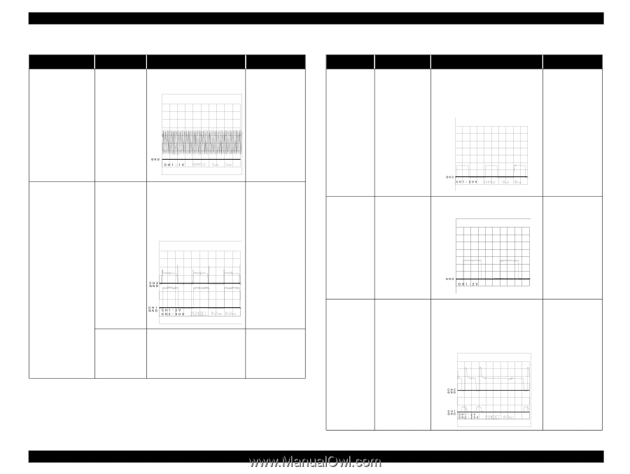
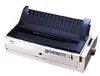
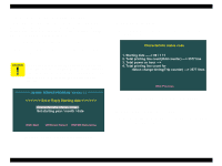
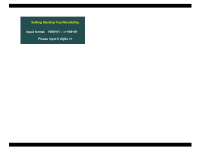
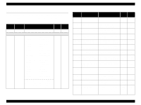
LQ-2080 Table 5-3. Repairing the C272MAIN Board (2/3) Problem Cause Checkpoint Solution The printer does CR1 is not operate at all. defective. Check the oscillator signal at pins 26 or 27 of the CPU. If the signal is not correct, replace IC4 (or replace the main board). Otherwise, replace CR1. Carriage operation is abnormal. IC11 or IC4 is defective. • Check input signal waveform (CH1) at pins 6, 5, 17, and 16 of IC11. • Check output signal waveform (CH2) at pins 8, 1, 18, and 11 of IC11. If the input signal is not correct, replace IC4 (or replace the main board). If the output signal is not correct, replace IC11. Revision A Table 5-4. Repairing the C272MAIN Board (3/3) Problem Cause Checkpoint Solution Paper feed is abnormal. IC3 is defective or IC12 is defective. • Check input signal waveform at pin 8 of IC12. • Check output signal waveform at pins 1, 2, 23, and 24 of IC12. If the input signal is not correct, replace IC1 or IC2 (or replace the main board). If the input signal is correct and the output signal is not correct, replace the IC11. No data is printed. IC4 is defective. Check the output signal waveform at pin 15 of IC4. If this signal is not output, replace IC4 (or replace the main board). IC4 is defective. Check the output signal at pins 1 to 4 of IC4. If there is no output signal, replace IC4 (or replace the main board). A particular dot fails to print. IC3 is defective or one of the head drive transistors is defective (Q1 Q24). • Check the voltage waveform (CH1) at port HD1 - HD24 of IC3. • Check the voltage waveform (CH2) for each transistor. If the head drive signal is not output, replace IC3 (or replace the main board). If the head drive signal is output from the head drive transistors, replace the head drive transistor. Troubleshooting Repairing the C273 Main Board 43
-
 1
1 -
2
-
3
-
4
-
5
-
6
-
7
-
8
-
9
-
10
-
11
-
12
-
13
-
14
-
15
-
16
-
17
-
18
-
19
-
20
-
21
-
22
-
23
-
24
-
25
-
26
-
27
-
28
-
29
-
30
-
31
-
32
-
33
-
34
-
35
-
36
-
37
-
 38
38 -
 39
39 -
 40
40 -
 41
41 -
 42
42 -
 43
43 -
 44
44 -
 45
45 -
 46
46 -
 47
47 -
 48
48 -
49
-
50
-
51
-
52
-
53
-
54
-
55
 |
 |