Epson 2080 Service Manual - Page 36

Bi-D Adjustment - lq impact printer

Page 36 highlights

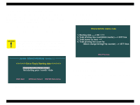
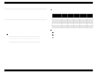
LQ-2080 4.1.2 Bi-D Adjustment This adjustment is made after the main board or the CR motor has been replaced. The purpose of this adjustment is to electrically correct the head wire's point of impact during Bi-D printing. The adjusted value is stored in the specific address in the EEPROM. Once the value is stored, it will not be erased if the printer is turned off or the EEPROM is reset. If the printer is in the emulation mode, characters output for the Bi-D adjustment will be garbled. If so, turn ESC/P2 on using the EEPROM Initialization mode. 1. Perform the pre-operation. (See Section 4.1.1.) 2. Select "1. Bi-D Adjustment". The following screen appears. Revision A The value "0" shown in the screen shown in Figure 4-5 is the initial value used in the program, which varies from the one stored in the EEPROM. However, if the main board has been replaced, the value in the EEPROM is replaced with "0"as the initial value. The printing pattern below is a sample for the high speed mode. Be sure to perform the adjustment in draft copy mode and LQ mode as well. Figure 4-5. Initial Menu of the Bi-D Adjustment 3. Press the Space key to check the current Bi-D setting condition for the draft mode. The printer prints the following pattern. Figure 4-6. Bi-D Pattern Sample 4. Output the patterns for the Draft Copy Mode and the LQ Mode, the rest of the three modes in the screen (Figure 4-5). Then check that the vertical lines in the middle row for each mode are aligned. (If no adjustment is needed, you can turn the printer off, not continuing to the next step.) 5. Examine the patterns for the three modes output in the previous steps, and correct the value in the screen shown in Figure 4-5 until the vertical lines for the center value (Data = 0 in Figure 4-6) are aligned. Adjustment Overview 36

  • 1
  • 2
  • 3
  • 4
  • 5
  • 6
  • 7
  • 8
  • 9
  • 10
  • 11
  • 12
  • 13
  • 14
  • 15
  • 16
  • 17
  • 18
  • 19
  • 20
  • 21
  • 22
  • 23
  • 24
  • 25
  • 26
  • 27
  • 28
  • 29
  • 30
  • 31
  • 32
  • 33
  • 34
  • 35
  • 36
  • 37
  • 38
  • 39
  • 40
  • 41
  • 42
  • 43
  • 44
  • 45
  • 46
  • 47
  • 48
  • 49
  • 50
  • 51
  • 52
  • 53
  • 54
  • 55

LQ-2080
Revision A
Adjustment
Overview
36
4.1.2
Bi-D Adjustment
This adjustment is made after the main board or the CR motor has been
replaced. The purpose of this adjustment is to electrically correct the
head wire’s point of impact during Bi-D printing. The adjusted value is
stored in the specific address in the EEPROM. Once the value is stored,
it will not be erased if the printer is turned off or the EEPROM is reset.
1.
Perform the pre-operation. (See Section 4.1.1.)
2.
Select “1. Bi-D Adjustment”. The following screen appears.
Figure 4-5.
Initial Menu of the Bi-D Adjustment
3.
Press the Space key to check the current Bi-D setting condition for
the draft mode. The printer prints the following pattern.
Figure 4-6.
Bi-D Pattern Sample
4.
Output the patterns for the Draft Copy Mode and the LQ Mode, the
rest of the three modes in the screen (Figure 4-5
)
. Then check that
the vertical lines in the middle row for each mode are aligned. (If no
adjustment is needed, you can turn the printer off, not continuing to
the next step.)
5.
Examine the patterns for the three modes output in the previous
steps, and correct the value in the screen shown in Figure 4-5 until
the vertical lines for the center value (Data = 0 in Figure 4-6) are
aligned.
C
A
U
T
I
O
N
If the printer is in the emulation mode, characters
output for the Bi-D adjustment will be garbled. If so,
turn ESC/P2 on using the EEPROM Initialization mode.
*
*
*
*
*
*
*
*
*
*
*
*
*
*
L
Q
-
2
0
8
0
S
E
R
V
I
C
E
P
R
O
G
R
A
M
V
e
r
s
i
o
n
1
.
1
*
*
*
*
*
*
*
*
*
*
*
*
*
*
<
B
i
-
D
a
d
j
u
s
t
m
e
n
t
>
D
r
a
f
t
M
o
d
e
D
r
a
f
t
C
o
p
y
M
o
d
e
L
Q
M
o
d
e
P
r
e
v
i
o
u
s
[
E
S
C
]
=
0
=
0
=
0
P
r
i
n
t
o
u
t
[
S
P
A
C
E
]
S
e
l
e
c
t
s
p
e
e
d
[
U
p
/
D
o
w
n
]
A
d
j
u
s
t
v
a
l
u
e
[
L
e
f
t
/
R
i
g
h
t
]
W
r
i
t
e
t
o
E
E
P
R
O
M
[
E
N
T
E
R
]
C
A
U
T
I
O
N
The value “0” shown in the screen shown in Figure
4-5 is the initial value used in the program, which
varies from the one stored in the EEPROM. However,
if the main board has been replaced, the value in the
EEPROM is replaced with “0”as the initial value.
The printing pattern below is a sample for the high
speed mode. Be sure to perform the adjustment in
draft copy mode and LQ mode as well.
D
r a ft m
o d e
B
i- D
d a ta
=
-1
D
r a ft m
o d e
B
i- D
d a ta
=
-0
D
r a ft m
o d e
B
i- D
d a ta
=
1