Epson EPL-N1200 Product Information Guide - Page 4
INSTALLING AN INTERFACE CARD, Hardware Configurations.
 |
View all Epson EPL-N1200 manuals
Add to My Manuals
Save this manual to your list of manuals |
Page 4 highlights
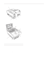
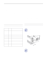
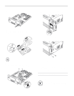
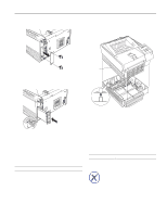
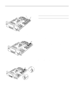
EPSON EPL-N1200 4. Remove the plastic connector cover from the controller board bracket. 7. Position the controller board so its components face the side panel of the printer and align it with the top and bottom guide rails in the printer. Then slide in the board. 5. Now set the jumper and slide switch settings on the LocalTalk/Serial module for the type of interface you'll be using: RS-232C serial, current loop serial, or LocalTalk (default). 8. Secure the controller board bracket with the four screws you removed earlier. Caution: Make sure both slide switches are set to the same position or the printer will not operate correctly. 6. Position the module as shown below; then align its connector with connector CN4 on the controller board. Secure the module with the two screws that came with it. 9. Connect the appropriate cable to the module through the hole you exposed in step 4. 10.Plug the power cord into an electrical outlet; then turn on the printer. To verify that the interface is working properly, print a status sheet and make sure your interface is listed under "Hardware Configurations." Installing an Interface Card 1. Turn off the printer and unplug the power cable from the electrical outlet. Warning: To avoid electrical shock, do not remove the interface slot cover unless the printer is turned off and unplugged from the electrical outlet. 4 - EPSON EPL-N1200 1/97
-
 1
1 -
 2
2 -
 3
3 -
 4
4 -
 5
5 -
 6
6 -
 7
7 -
 8
8 -
 9
9 -
 10
10 -
11
-
12
 |
 |
