Eureka LightSpeed 4700D Owners Manual - Page 12
FIG. 7, FIG. 8, FIG. 9 - vacuum
 |
View all Eureka LightSpeed 4700D manuals
Add to My Manuals
Save this manual to your list of manuals |
Page 12 highlights
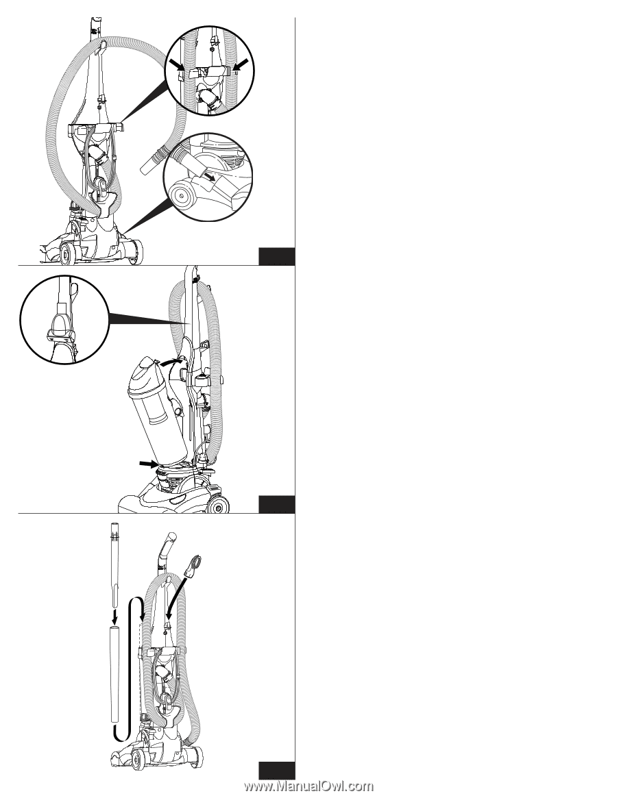
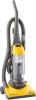
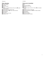
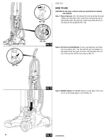
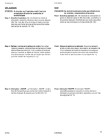
●G ●H FIG. 8a ●F FIG. 7b ENGLISH HOW TO ASSEMBLE (continued) Step 7: Then wrap the hose up and over the hose hook on the handle ●G as shown. Plug the end of the hose into the hose retainer hole on the base ●E (FIG. 7a) and then snap the hose into the hose holder on the tool caddy ●H (FIG. 7b). ●E FIG. 7a FIG. 7 Step 8: Place the dust cup ●F on the vacuum by aligning the bottom groove of the dust cup against the tab on cleaner base. Pivot the dust cup up against cleaner and push to secure as it snaps into place (FIG. 8). Step 8A: (in some models only). Place Power Paw™ stair brush in slot in the special handle holder (FIG. 8). FIG. 8 ●B Step 9: Place the wand/crevice ●A /●B tool in the wand holder on the side of the vacuum. Store the dusting brush ●C on the brush holder on the back of the handle (FIG. 9). ●C Note: Screws must be installed to properly secure the parts of the vacuum. ●A 12 FIG. 9
-
 1
1 -
2
-
3
-
4
-
5
-
6
-
 7
7 -
 8
8 -
 9
9 -
 10
10 -
 11
11 -
 12
12 -
 13
13 -
 14
14 -
 15
15 -
 16
16 -
 17
17 -
18
-
19
-
20
-
21
-
22
-
23
-
24
-
25
-
26
-
27
-
28
-
29
-
30
-
31
-
32
-
33
-
34
-
35
-
36
 |
 |