Fisher and Paykel RS36A72J1 Installation Manual - Page 15
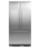
Top Panel - Rear View, Bottom Panel - Rear View
 |
View all Fisher and Paykel RS36A72J1 manuals
Add to My Manuals
Save this manual to your list of manuals |
Page 15 highlights
7 CUSTOM DOOR PANEL DIMENSIONS The drawings below apply to non-Water dispensing models only. Dimensions are shown in Imperial (inches) and apply for the preparation and installation of custom door panels. For Dwg and Dxf files of the below panel preparation download the folder on http://thekitchentools.fisherpaykel.com 15 7/16 2 5/32 Ø 3/32 REF 12x Pilot holes recommended for bracket attachment. (Do not penetrate front surface). Ensure handle is mounted 2 9/16" from inner edge of panel to the center - this will avoid interference with brackets. All measurements to be made from inner bottom corner. For the second panel mirror and repeat dimensions using 1 3/8 inner bottom corner as the reference point. 16 5/16 TOP PANEL - REAR VIEW 40 38 5/8 26 29/32 24 15/16 4 31/32 6 15/16 3 7/16 1 5/32 21 11/32 19 3/8 15 5/32 5 1/32 Ø 3/32 REF 10x Pilot holes recommended for bracket attachment. (Do not penetrate front surface). All measurements to be made from top and centerline. 16 3/8 Ensure handle screw heads are counter sunk into back of panel to avoid interfering with hanging bracket. BOTTOM PANEL - REAR VIEW 13
-
 1
1 -
2
-
3
-
4
-
5
-
6
-
7
-
8
-
9
-
 10
10 -
 11
11 -
 12
12 -
 13
13 -
 14
14 -
 15
15 -
 16
16 -
 17
17 -
 18
18 -
 19
19 -
 20
20 -
21
-
22
-
23
-
24
-
25
-
26
-
27
-
28
 |
 |
